IDA8 Global-Net User Manual426
© 2020, ATEÏS. All rights reserved.
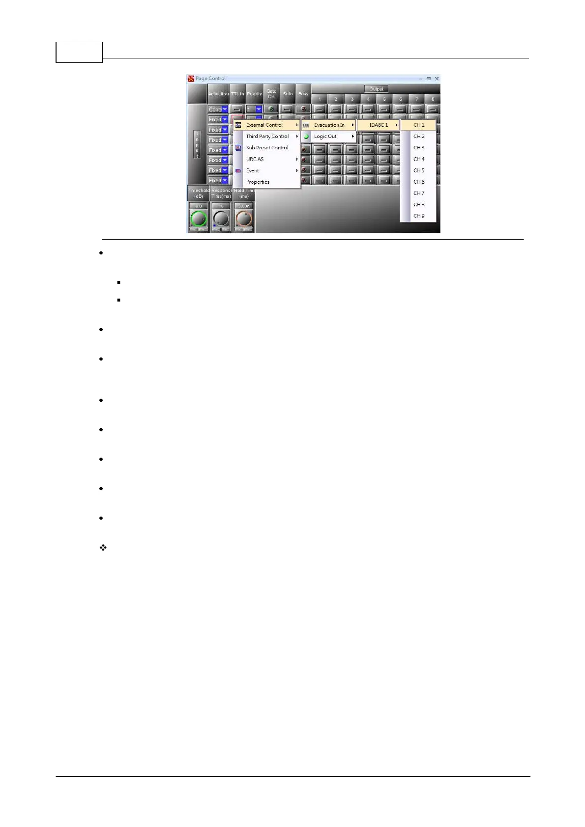
Priority: When multiple input channels are being triggered, the channel which has higher priority
and will be routed first.
The smaller the number is, the higher the priority is.
The priority basis will be based on first-in, first-served if the priority among the conflicted input
channels are the same.
Gate On LED: This LED will light up when the input channel is triggered and its gate of routing is
activated.
Solo: Activate the [Solo] button to forbid other input channels to route to output channel if an input
channel has been activated to route to output channels, even though the chosen output channel of
each input channel does not conflicted.
Busy: Light up if the gate of input channel is open, but this channel can not be routed because the
other input channel with higher priority has been activated already.
Output (channel output): The chosen output channel(s) will be routed when the input channel is
activated
Threshold (dB): When the level of input channel is above this [Threshold] setting, the gate of
routing will be activated.
Response Time (ms): If the level of input channel is continually greater than the [Threshold], and
has passed the [Response time] setting, the gate will be opened.
Hold Time (ms): If the level of input channel is less than the [Threshold], this [Hold time] setting is
to keep the gate continually open after no input signal is detected.
Application
You cannot have two input channels mixed to an output (even if they have the same priority). In this
case, the busy LED of the lower channel number will light up and these channels won't be routed.
Each output works separately. On each one output, only the channels with the gate ON and with the
highest priority will be routed.
6.21.2 Network Paging (Matrix & Switch Mode)
The Network Paging component routes the input source signal to zones using priority arbitration. The
pins at the left represent the paging sources and the pins at the right are zones. The pins on top
allow to control the paging activity and the pins on the bottom are the output logic signals which tell
the status of paging activity.
 Loading...