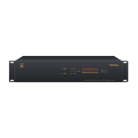
IDA8 Global-Net User Manual154
© 2020, ATEÏS. All rights reserved.
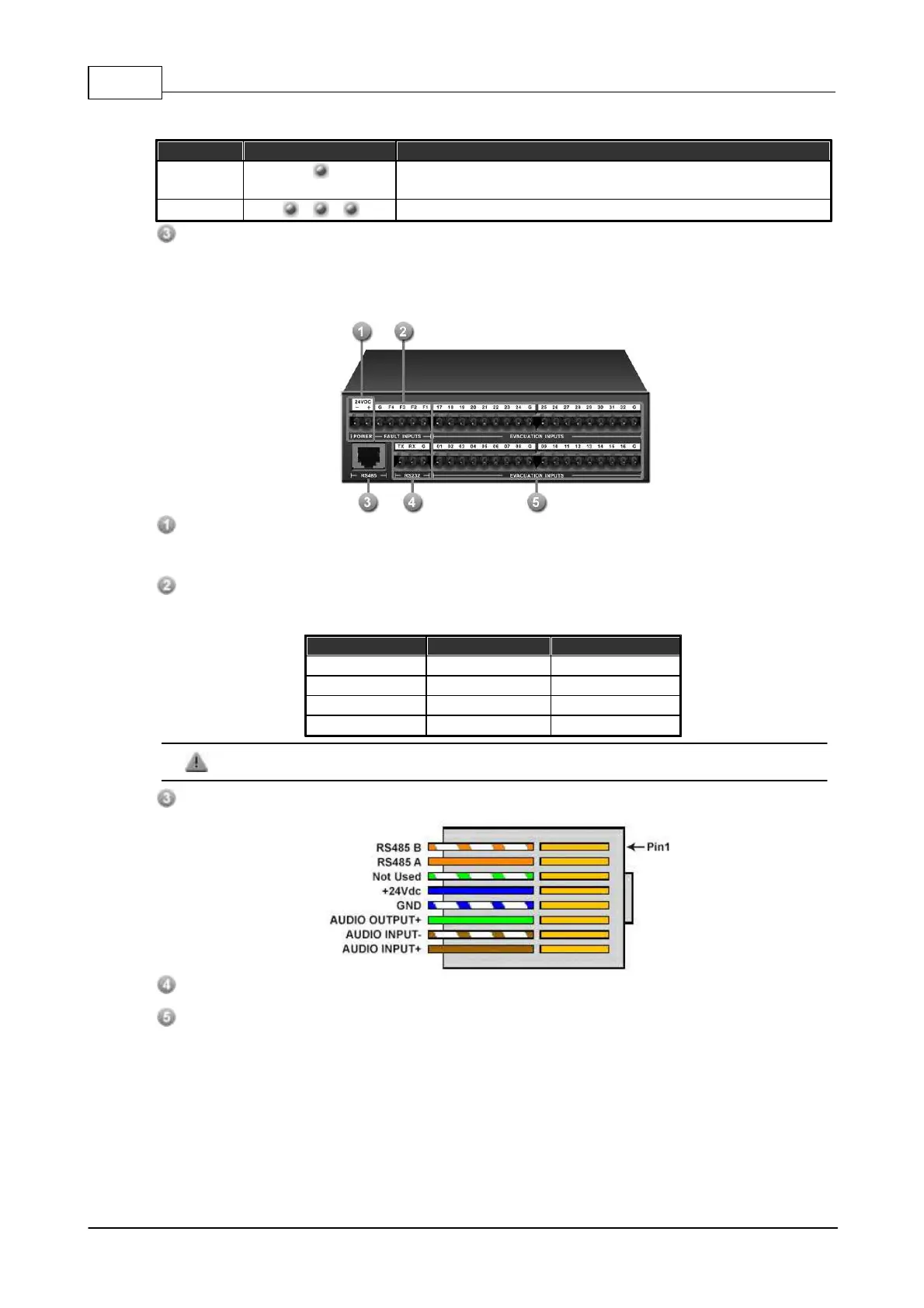
Display fault status of system. the following table lists the states of the Fault LED:
One of the the fault inputs is active.
One of the Evacuation inputs is Short Circuit or Line Open
Blinks 5 times after powered on.
Power LED:
Light up in green when the device is powered.
3.2.6.2 Rear Panel
24V DC Input:
Main 24VDC power supply connector.
Fault Inputs:
4 fault inputs received logic signals and used as switches. See the table and figure below:
Do not input the external power voltage to this connector, it might damage the device.
RS485 Connector: 8C8P RJ45 connector for RJ45 connection.
RS232 Connector
Evacuation Inputs:
32 evacuation contact inputs for expanding the channels for IDA8 system. The following table
and figure show the status of the inputs.
 Loading...