IDA8 Global-Net User Manual392
© 2020, ATEÏS. All rights reserved.
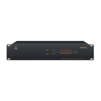
Event Name: The name of the events that are
linked.
Content: A [...] link button to open the setting
window.
State: The item of the element which you want to
trigger an event.
Logic In: Choose the type of trigger either raising
edge(Lo to Hi) or falling edge(High to Lo), or both
you want.
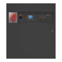
Logic Out: Define the state of output signal. There
are two cases which need to be considered
whether the event is proceeded successfully or
not. To finish this configuration, first, you need to
select the output signal what is function/working,
see the picture on the right.
From the above picture, the logic output of
channel 4 and 6 are selected. For more
settings, click the [...] grid on [Logic Out].
From the above figure, the settings indicates
when [Event 1] is Failed, Output 4 will be 1
and Output 6 will be 0, and when [Event 1] is
successfully triggered, the Output 4 will be 0
and Output 6 will be 1.
The Value Trigger/Step Trigger/Master
Preset Change/Sub-Present Change can
be modified by Event Trigger component
only.
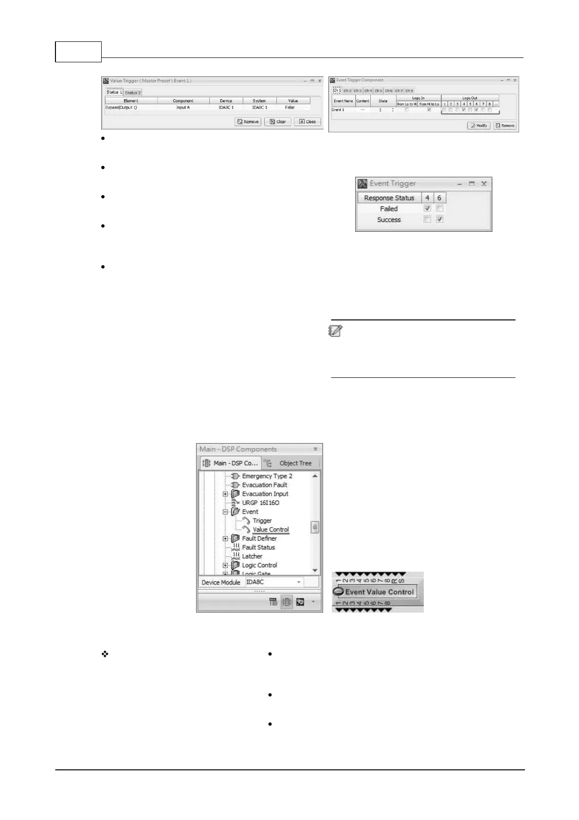
6.13.10.2 Value Control
This component link events to logic signal, linked events will be triggered if any input logic signal
changes.
Control Window
When the Value Control component is
dragged from [Main-DSP
Components], a [Component Setting]
window will display as the picture
below.
Repeat Pin: Click to add a R Pin as the indication if the
value is the same and wants to repeat the trigger events.
Sign Pin: Click to add a Sign Pin if the triggering value
includes the minus value.
Input Channel: The number of input which is available in
the binary range.
 Loading...