IDA8 Global-Net User Manual398
© 2020, ATEÏS. All rights reserved.
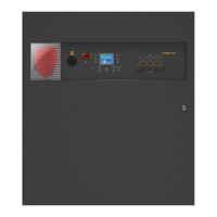
6.13.16 Logic Net Input
This component transfers logic signals over Ateis Net. The logic signal goes into the Logic Net Out
component in one device and out from the Logic Net In component in another device by using the
Ateis Net card.
The signal path is one-to-many and there are 48 channels available to carry signals which are
numbered and identified by number. For example, a signal goes into channel 1 of Logic Net Out A
component and will go out from the channel 1 of Logic Net In A component.
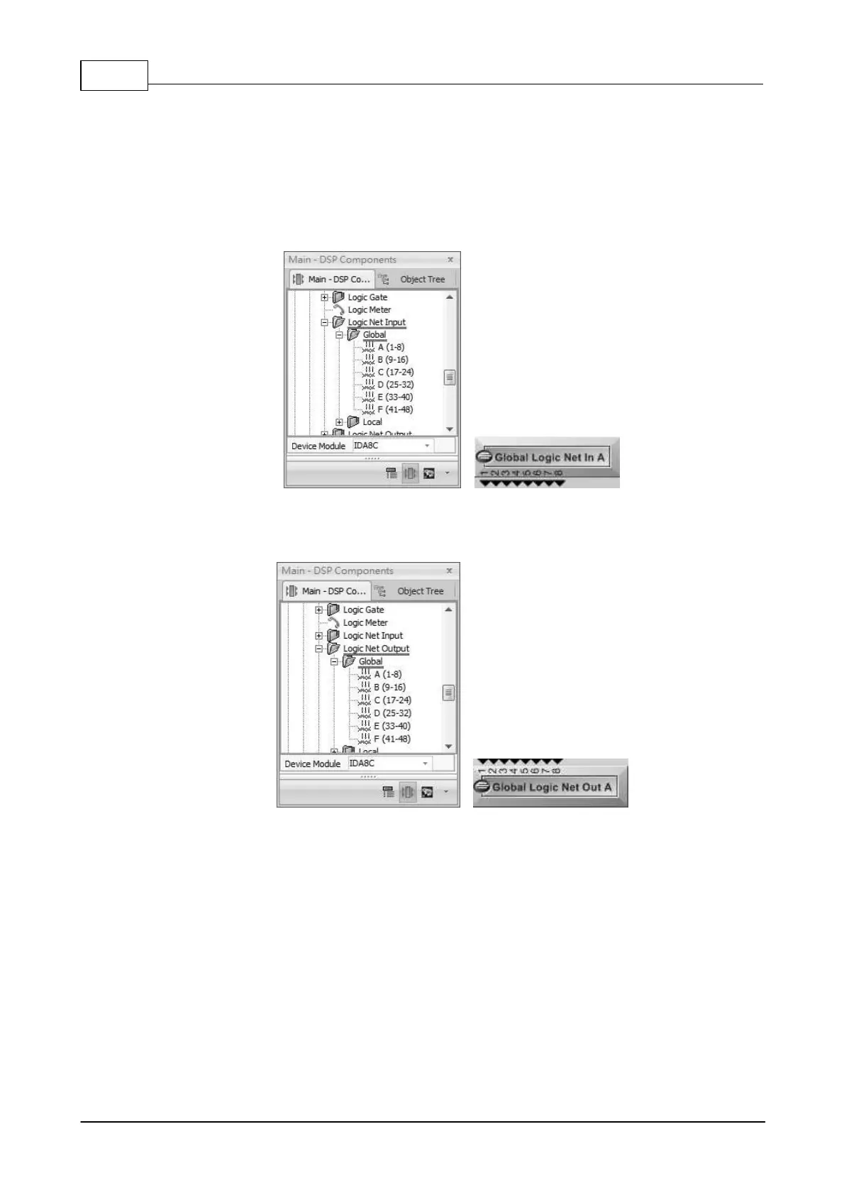
6.13.17 Logic Net Output
This component transfers logic signals over Ateis Net.
6.13.18 Logic Pulse Control
The Pulse Control component allows to have a duration of 1 second for pulse output when the status
of Input Pin has been changed. Please see the picture below,
 Loading...