IDA8 Global-Net User Manual396
© 2020, ATEÏS. All rights reserved.
Fault LED: This LED will light up in red when the fault is generated.
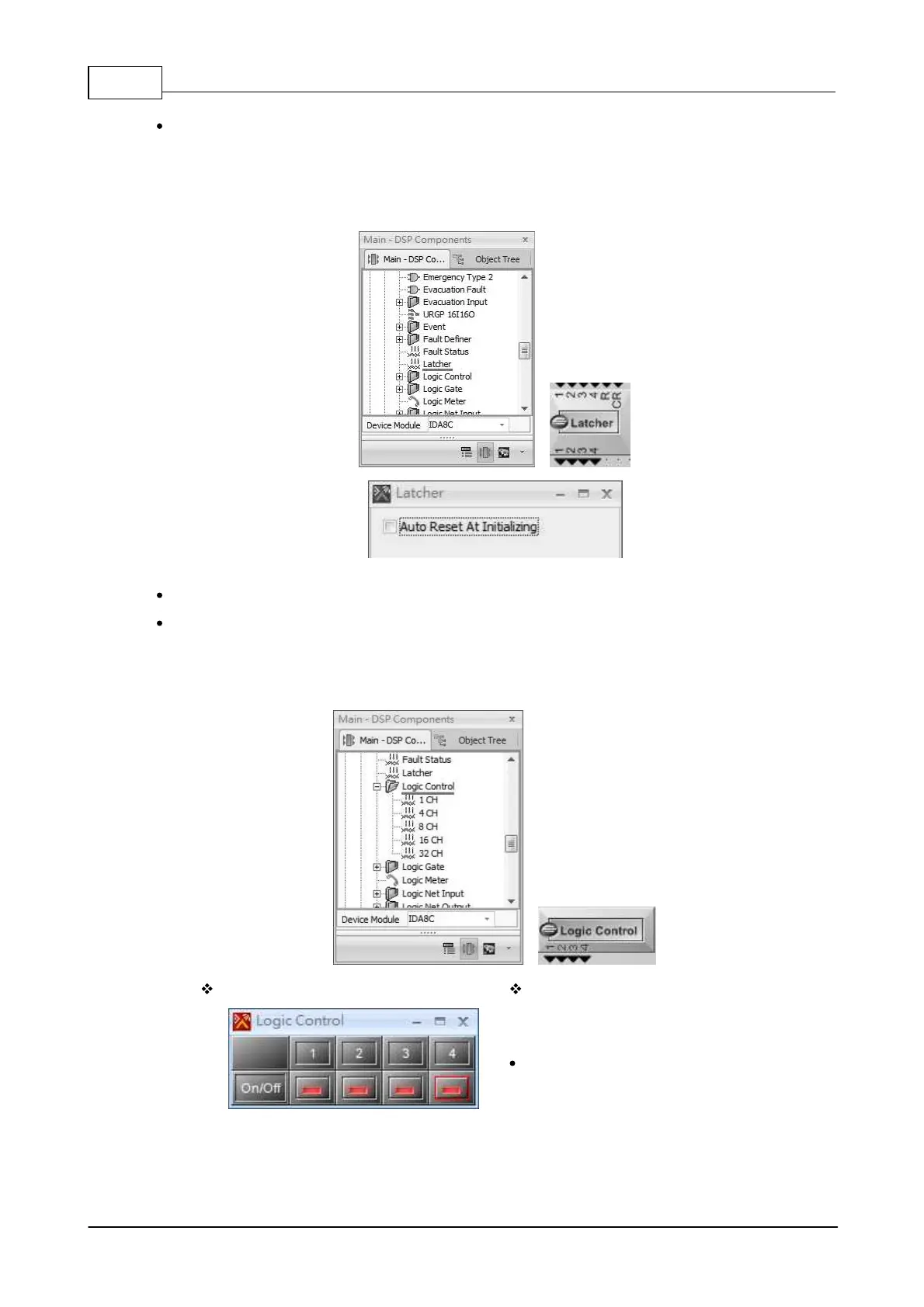
6.13.12 Latcher
Allow to lock the status of output, and the setting can be reset by clicking the [Auto Reset
Initializing] button. See the picture below,
R (Reset) pin: The triggering signal, which will lock after reset (mapping with R pin).
CR (Clear) pin: A pulse action based on the [Disable] mode, providing the function of lock.
6.13.13 Logic Control
Allow to generate the logic signal using buttons in Ateis Studio.
Elements
The element allows to show the control
logic signal for each channel output.
On/Off: Output logic signal 0 or 1.
 Loading...