System Products 173
© 2020, ATEÏS. All rights reserved.
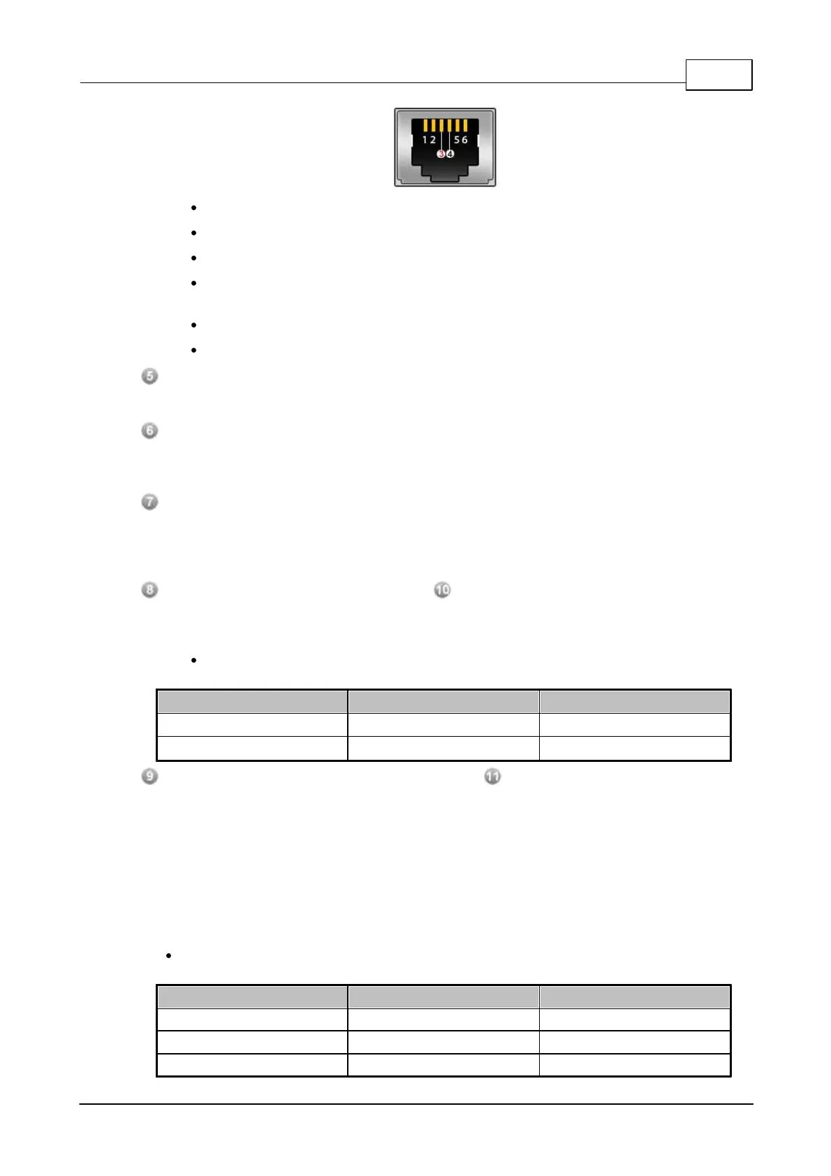
PIN1: NC
PIN2: NC
PIN3: TIP (0V)
PIN4: RING (-48V on hook ). The monitoring range is from -40 to -57V, under or over the
value might cause some problems.
PIN5: NC
PIN6: NC
Telephone Line Audio Output for Record:
Audio output of active telephone line.
Active Control Expansion Output:
This port output logic signal to next RU devices to synchronize redundancy state which tells
primary or secondary is active.
Fault:
This port is a logic contact, which is normally closed, opened if the unit is set to be slave (refer
to Master/Slave Switch of later item), and a short or open is detected on S_WD (Secondary
Watching Dog) port.
S_ACT (Secondary Active Contact Output) / P_ACT (Primary Active Contact Output):
The S_ACT and P_ACT contact outputs will inform the external device whether the primary or
secondary is active.
For example, when the RU status switches to the primary, the P_ACT is close contact,
and S_ACT is open contact.
S_WD (Secondary Watching Dog Contact Inputs) / P_ACT (Primary Watching Dog Contact
Inputs):
Connect the P_WD and S_WD inputs to the the Bypass Mode output on IDA8 processor. When
IDA8 enters the bypass mode, the Bypass Mode output will inform the RU units, and the RU unit
will determine whether to activate the primary IDA8 or the secondary IDA8 processor by the
monitored P_WD and S_WD contact inputs.
The basic philosophy is that the master RU unit monitors the P_WD and S_WD inputs coming
from the primary and secondary IDA8 processors and decide which one can be active, and also
passes the decision to next RU units through EXP_OUT terminal. See the table as below.
For example, when RU detects P_WD and S_WD contact are closed, it switches to the
primary.
 Loading...