892-0000010B OM
111
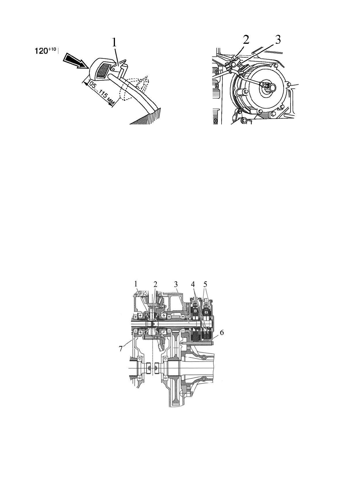
1 – connection bar; 2 – adjusting bolt; 3 – locknut.
Figure 3.7.3 – Adjustment of service brake control
ATTENTION: GETTING OF LUBRICANT INTO THE DRY FRICTION BRAKE CAUSES
OILING OF THE DISKS, REDUCTION OF THE FRICTION FORCE BETWEEN THEIR
WORKING SURFACES - THE BRAKES "DO NOT HOLD". IN THIS CASE, DISASSEMBLE
THE BRAKE, ELIMINATE OIL LIAKAGE AND WASH OILED DISCS WITH PETROL AND
LET THEM DRY FOR 5 TO 8 MINUTES. AFTER ASSEMBLY, ADJUST THE SERVICE
BRAKE CONTROL AS INDICATED ABOVE!
3.7.3 Parking brake
A separate brake with a manual independent drive to the rear wheels is used as a
parking brake. Parking brake type is dry.
The parking brake is mounted on the right service brake casing. When the tractor is
moving, the rotation from differential cross 2 (Figure 3.7.4) is transmitted to brake disks 5
through shaft 3. As you pull parking brake lever 17 (Figure 3.7.5), pressure discs 4 (Figure
3.7.4), while turning relative to each other, move apart, braking disks 5 and shaft 3 con-
nected to them and connected to differential cross 2, locking axle shaft gears 7 of the differ-
ential, axle and final drives and tractor wheels through planet gears. The parking brake may
be used for a short time to brake the tractor in case of failure of the service brakes.
1 - planet gear; 2 – differential cross; 3 - parking brake shaft; 4 – pressure disks; 5 - brake
disks; 6 - parking brake housing; 7 – axle shaft gear.
Figure 3.7.4 - Parking brake assembly