892-0000010B OM
63
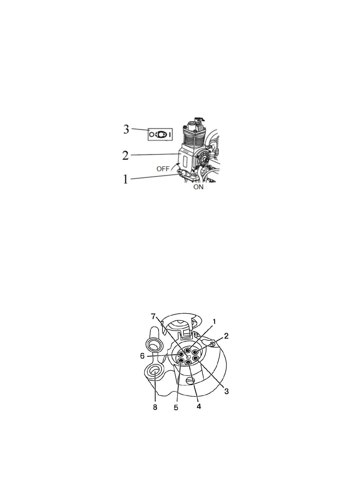
2.20 Pneumatic compressor control
The handle for turning on the compressor of the pneumatic system 1 (Figure 2.20.1)
has two positions:
- left (arrow on the handle is directed forward along the tractor) - "the compressor is
off";
- right (arrow on the handle is directed back, towards the tractor cab) - "the compres-
sor is on".
ATTENTION: TURN THE PNEUMATIC COMPRESSOR ON AND OFF ONLY WHEN
THE ENGINE IS OFF, OR AT THE MINIMUM IDLING OF THE ENGINE!
1 – handle for turning on the compressor of the pneumatic system; 2 – pneumatic
compressor; 3 – pneumatic compressor control diagram.
Figure 2.20.1 – Pneumatic compressor control
Note – Figure 2.20.1 shows the position “pneumatic compressor is off”.
2.21 Connection parts of electrical equipment
2.21.1 Socket for connecting the electrical equipment of attached agricultural im-
plement
A standard 7-pin socket with an additional port for connection of a porTable lamp
(Figure 2.21.1) is designed to connect current consuming equipment of a trailer or a trailed
agricultural implement. It is installed on the rear post of the cab. A plug of the wiring harness
of the trailer or attachable machines is connected to the socket.
1 - left turn flasher; 2 - horn; 3 - ground; 4 - right turn flasher; 5 - right marker light; 6 –
brake light; 7 - left marker light; 8 - socket for connection of a porTable lamp or other elec-
trical elements with current consumption up to 8A.
Figure 2.21.1 - assignment of terminals of a seven-pin socket with an additional port
for connection of a porTable lamp