892-0000010B OM
107
3.5.3 External re-adjustment of brake bands
In operation, re-adjust the PTO brake bands if the above adjustment of clearance in
the PTO band brakes does not result in the elimination of PTO slippage (adjustment reserve
has been taken up (significant wear of the brake band linings)).
When assembling the rear PTO planetary gear unit at the factory or during repair,
eccentric axle 3 (Figure 3.5.1) should be installed with its flat vertically on the right and fixed
with locking plate 12 and bolt 13;
To re-adjust the brake bands, unscrew adjusting screws 11 by five to seven turns,
turn eccentric axle 3 of the external re-adjustment mechanism by 180 degrees (flat on the
left), fix with locking plate 12 and bolt 13. Adjust clearances in the band brakes again ac-
cording to subsection 3.5.2 "Adjustment of clearance in PTO band brakes".
If the problem persists, replace the PTO belts.
ATTENTION: THE OPERATION OF REPLACING THE PTO BELTS IS TO BE PER-
FORMED ONLY BY DEALERS IN A DEDICATED WORKSHOP!
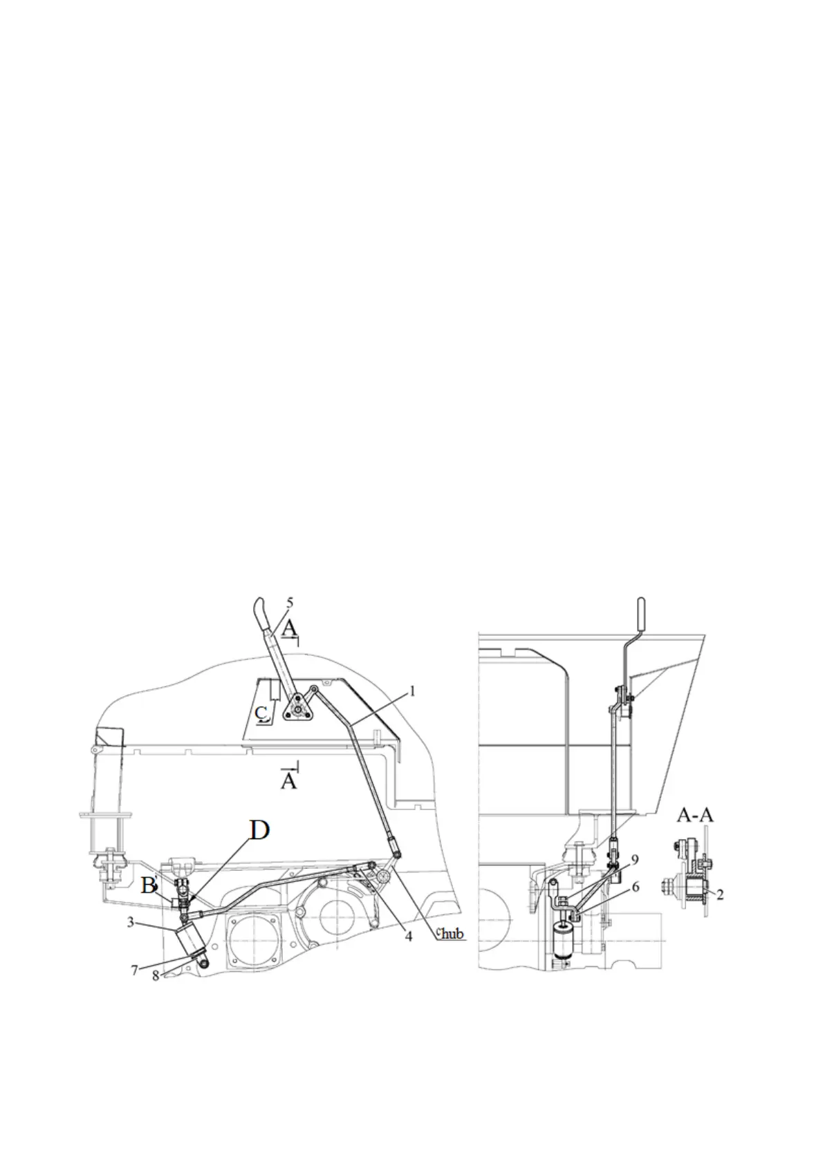
3.5.4 Rear PTO control
The tractor is equipped with a mechanical control of the rear PTO. The rear PTO control
diagram is shown in Figure 3.5.2.
Lever 5 has two positions:
- "PTO on" - rearmost position;
- "PTO off" - extreme forward position.
Lever 5 should be set and fixed in two extreme positions only under the action of spring
7. Post-pushing it by hand is not allowed.
Dimension C should be equal to 35
+10
mm (Figure 3.5.2) with lever 5 in the rearmost
position (Figure 3.5.2). Dimension C is adjusted by changing the length of rods 1 and 4. To
change the length of rods 1 and 4, it is necessary to unlock the nut and turn the yoke by a few
turns in the required direction to obtain dimension C (35
+10
mm).
1 – rod; 2 – bracket; 3 – cover; 4 – rod; 5, 6 – lever; 7 – spring; 8 – eye; 9 – bolt.
Figure 3.5.2 – Mechanical control of PTO