892-0000010B OM
136
- when carrying out transportation work and operations, when the front end of the
upper link is not connected to the machine or implement, install the upper link of the linkage
on the lower hole of the clevis (position "C" in Figure 2.16.2).
3.12.2.4 Lower links
3.12.2.4.1 General information
Tractors with a draft control unit can be equipped with detachable normal, detacha-
ble short or telescopic lower links with pivots.
On tractors with the draft control unit, additional lower link axles are installed, which
can be used to perform certain types of work. When rearranging the front ends of the lower
links from the main axles to the additional axles of the lower links, it is necessary to re-
adjust the lengths of the lifting rods and locking the buckles in the transport and working
position.
Installation of detachable short lower links with a length of 805 mm increases the
load capacity of the RLL by about 10% while reducing the lifting height by about 10%.
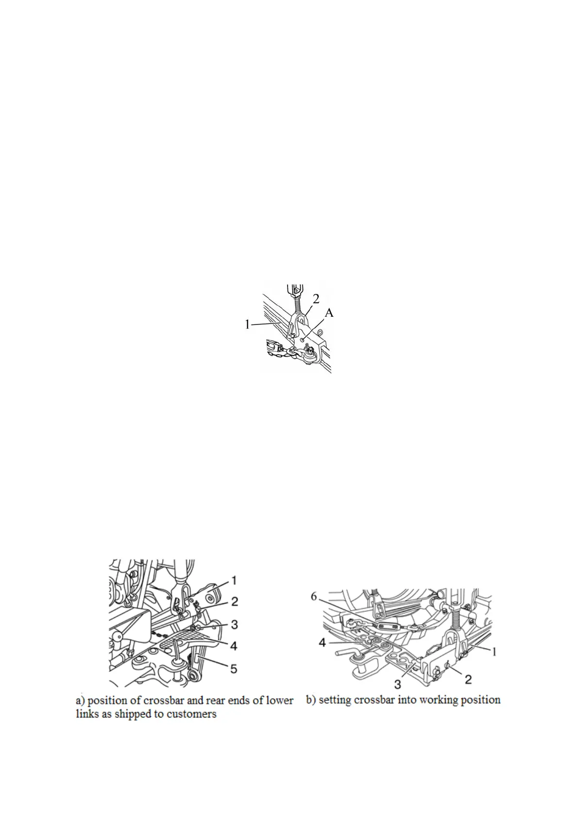
At the front ends of split lower links 1 (Figure 3.12.10), an additional point “A” is
provided. Attachment of the lifting rod to the additional point "A" increases the load capacity
of the RLL by approximately 10%.
1 – front end of lower link; 2 – lifting rod; А – additional attachment point for lifting rod.
Figure 3.12.10 – Location of additional point
3.12.2.4.2 Setting the crossbar and the rear ends of the lower links into working position
The BELARUS-892/892.2 tractors with a draft control unit and detachable lower links are
shipped to customers with a crossbar (TSU-1Zh) and rear ends of the lower links, as shown in
view a) of Figure 3.12.11.
To set the crossbar in the working position (as shown in view b) of Figure 3.12.11) per-
form the following operations:
- unlock split cotter and remove eyelets 3 (Figure 3.12.11), remove crossbar 4;
- unlock split cotter and remove pins 2, remove rear ends of lower links 5;
- install crossbar 4 on the front ends of lower links 1, as shown in the view b) of Figure
3.12.11), secure it with the help of eyelets 3, pins 2 and split cotters;
- connect limiting buckles to eyelets 3.
1 – front ends of lower links; 2 – pin; 3 – eyelet; 4 – crossbar; 5 – rear ends of lower links; 6
– limiting buckle.
Figure 3.12.11 – Setting the crossbar in the working position