892-0000010B OM
135
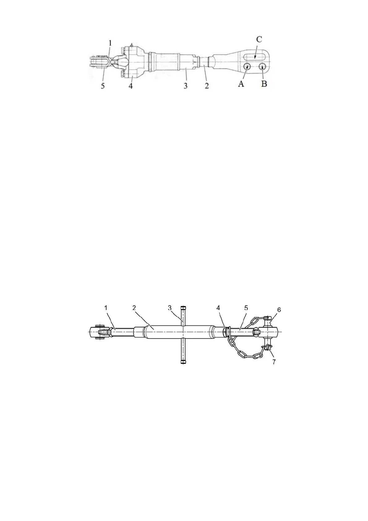
1 – handle; 2 – yoke; 3 – pipe; 4 – housing; 5 – shackle.
Figure 3.12.8 – Gear lifting rod
On tractors with a draft control unit, the length of the lifting rods (both screw and gear
type) is adjustable from 425 to 520 mm. As shipped from the factory, the lifting rods are
adjusted to a length of 475 mm.
To accelerate the change in the length of the lifting rods, two holes are provided on
their yoke (A and B in Figures 3.12.7 and 3.12.8) for installing a pin. To copy the relief of the
cultivated area of the field when working with wide-cut machines and to avoid damage to
the lifting rods, connect the lifting rods to the lower links through the grooves (C in Figures
3.12.7 and 3.12.8). In this case, the grooves of the lifting rod yoke must be behind the hole
along the tractor movement to avoid damage to the lifting rod.
When working with agricultural implements, adjust the length of the right lifting rod to
the depth of processing.
3.12.2.3 Upper link
The upper link is shown in Figure 3.12.9.
The length of the upper link can be adjusted from 500 to 740 mm.
Adjust the length of the upper link in the following sequence:
- unscrew locknut 4 (Figure 3.12.9);
- by rotating handle 3 of pipe 2 clockwise or counterclockwise, change the length of
the upper link;
- having adjusted the length of the link, lock the screw connection with locknut 4.
To attach the upper link to the implement, use pin 6 of the rear pivot, to fix the pin,
install split pin with ring 7 on it.
1 – front screw with pivot; 2 – pipe; 3 – handle; 4 – locknut, 5 – rear screw with
pivot; 6 – pin; 7 – split pin with ring.
Figure 3.12.9 – Upper link
On tractors with a draft control unit, depending on the type of work performed, the
following options for installing upper link 2 (Figure 2.16.2) in the holes of clevis 1 are recom-
mended:
- when using RLL in the draft control mode, install the upper link of the linkage on the
two upper holes of the clevis (positions "A" and "B" in Figure 2.16.2);
- when using the RLL in the position control mode, install the upper link of the linkage
on the upper hole of the clevis (position “A” in Figure 2.16.2);
- when using the RLL in the depth control mode, install the upper link of the linkage
on the bottom hole of the clevis (position “C” in Figure 2.16.2);