892-0000010B OM
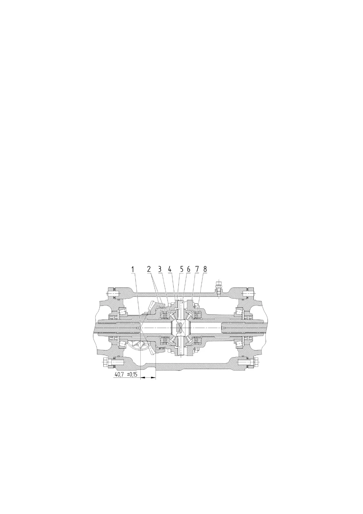
159
housing. Filling of the FDA shall be carried out on the horizontal surface. Hole for plug 14
also serves to fix the driven gear when checking the adjustment of the main gear meshing.
Hermiticity of the main gear cavity and the FDA beam is carried out by gaskets 3,
23 and by sealing rings 5, 19 installed in covers 2 and in main gear cage 20. To prevent oil
backing before the drive gear gasket, oil thrower ring 22 is installed on its spline end. Spi-
ral grooves are cut along the outer diameter of the groove. FDA body 8 is connected to the
beam by two hollow axes 13, on which the axle together with wheels can swing in trans-
verse plane, deviating for angles limited by the stops in covers 2 during their contact with
tractor beam. The axes are locked by planks 12 against axial movement.
3.16.1.2. FDA differential
This differential is installed both on BELARUS 892 and BELARUS 892.2 tractors.
Self-locking differential of increased friction. In housing 5 and cover 7 (Figure 3.16.2)
of the differential connected with bolts, two pairs of planetary gears 4 on floating shafts
6,axle shaft gears 1, pressure cups 3 and friction discs – drive 2 and driven 8 are located.
The self-locking differential automatically connects both half axles 16 (Figure
3.16.3), excluding separate slipping of wheels and increasing FDA traction force. The
differential lock is activated when the front axle is engaged. In this case planetary gear shafts
6 (Figure 3.16.2) turn under load and move along taper grooves in housing 5 and cover
7 of the differential accordingly to the size of the clearance between friction discs 2, 8. From
the shafts the force is transmitted to planetary gears 4, which transmit it with collars to cups
3, and they in turn compress friction discs against the stop to the walls of the body
and differential covers. Drive discs 2, having outer teeth, are connected to the teeth of the
body and the differential cover, and driven discs 8 (by inner teeth) – with axle shaft gears.
Friction force of the compressed discs integrates axle shaft gears and the body with
the differential cover, thus locking the differential. When turning the tractor, when the FDA is
engaged and the external forces exceed the friction forces in the friction discs, the friction
discs will slip.
The differential is mounted on two tapered roller bearings 11 (Figure 3.16.1) in covers
2 of the FDA beam. The differential bearings are adjusted by shims 4 (Figure 3.16.1).
1 – axle shaft gear; 2 – drive discs; 3 – pressure cup; 4 – planetary gear; 5 – differen-
tial housing; 6 – planetary gear shaft; 7 – differential cover; 8 – driven disc; 9 – adjusting
shims; 10 – driven gear; 11 – drive gear.
Figure 3.16.2 – FDA differential
3.16.1.3 Bevel wheel gear group
Wheel gear group is intended to transmit torque from the FDA differential to the
drive steering wheels. The composition of the bevel wheeled group is shown in Figure
3.16.3.
In covers 2 (Figure 3.16.1) of the FDA beam the wheel gear group of final drives
is installed, consisting of the two bevel gears and pinions – upper and lower, which at the
same time serve as joints of equal angular speeds, as well as bracket 34 of the front