892-0000010B OM
69
2.25 Integrated indicator of tractors with a molded dashboard
2.25.1 General information
Integrated indicator 5 (Figure 2.23.1) (hereinafter II) and integrated indicator control
panel 7 (Figure 2.23.1) (hereinafter IICP) display information on operational parameters of
systems and units of the tractor and provide operator with data on violation of work or break-
down of any system.
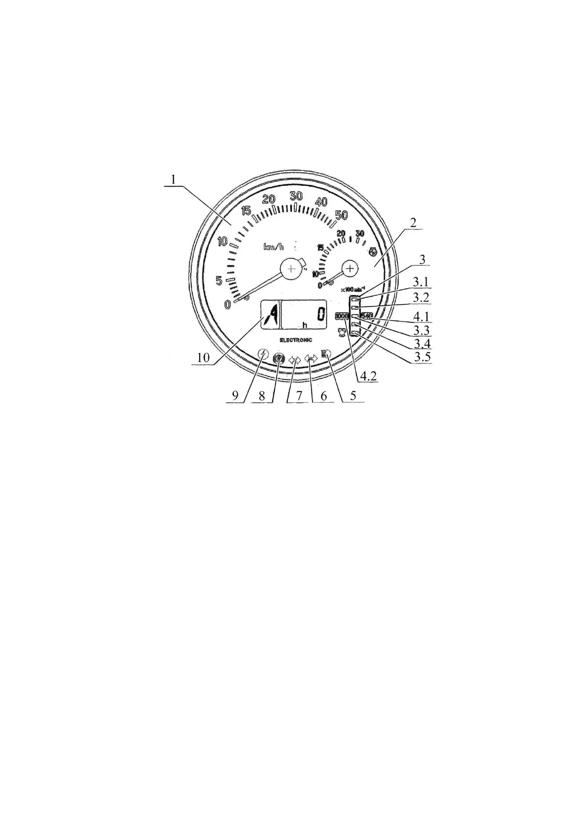
The II includes gauges and indication lamps as per Figure 2.25.1.
1 – velocity gauge (needle indicator);
2 – engine speed gauge (needle indicator);
3 – PTO speed gauge (light indicator);
3.1, 3.5 – segments of PTO speed scale (yellow color);
3.2, 3.3, 3.4 – segments of PTO speed scale (green color);
4.1, 4.2– annunciators of PTO speed scale range (yellow color);
5 – pilot lamp to indicate headlights upper beam (blue color);
6 – pilot lamp to indicate trailer turn blinkers (green color);
7 – pilot lamp to indicate tractor turn blinkers (green color);
8 – pilot lamp to indicate parking brake activation (red color);
9 – pilot lamp to indicate high voltage in on-board system (red color);
10 – multifunctional display.
Figure 2.25.1– Integrated indicator
2.25.2 Assignment and operation principle of integrated indicator gauges
а) Velocity gauge 1 (Figure 2.25.1) indicates a design speed of the tractor on a needle
indicator. The design speed exceeds the actual one, as tractor skidding is not taken into
account.
The gauge is actuated by signals coming from pulse sensors of rotation frequency of
toothed gears of final drives of right and left rear wheels. The speed is indicated in accord-
ance with the signal from the sensor installed on the final drive gear of the wheel, turning
with a less speed.
In case one of the speed sensors is faulty the integrated indicator shows speed read-
ings in accordance with the signal coming from the correct sensor. Specific faults of circuits
or speed sensors when the signals from them are missing are displayed in liquid crystal
display as “0” digit, characterizing the fault location – to the right or to the left (see below).
b) The engine speed gauge 2 (Figure 2.25.1) indicates rotation frequency of the en-
gine crankshaft on a needle indicator.