892-0000010B OM
70
On the BELARUS-892/892.2 tractors, the signal for calculating the engine speed is the sig-
nal of the phase winding of the alternator (terminal "W").The range of speed readings is from 0
to 3500 (rpm).
c) PTO speed gauge 3 (Figure 2.25.1) displays the PTO speed on a light indicator.
The PTO speed gauge is actuated by frequency signal, resulting from recalculation
of the signal from the alternator phase winding by means of entered value of index “KV2”
(see below), other than “0”, meanwhile the value of index “ZV” should be entered as equal
to “0” (see below).
When II is turned on (see the description of the device functional check below) and
the engine is running (signal from the alternator phase winding is coming) indications of
scales “540” and “1000” are illuminated simultaneously.
Indication of the PTO scale segment (with regard to the entered value of index “KV2”)
occurs when the PTO design speed, equal to 750 rpm, is achieved.
Indication of the PTO scale lower segment (with regard to index “KV2”) occurs when
the engine speed of 1400-1500 rpm and above is achieved.
Depending on selected PTO speed mode (540 or 1000) illuminated scale segments
identify value of PTO speed in accordance with Table 2.25.1
“PTO speed” mode of liquid-crystal display 10 of the multifunctional indicator (Figure
2.25.1) (see the description of the multifunctional display operation below) is not active in
this case.
Table 2.25.1
«540» «1000» Location of seg-
ment on scale
650 1150 3.1
580 1050 3.2
500 950 3.3
420 850 3.4
320 750 3.5
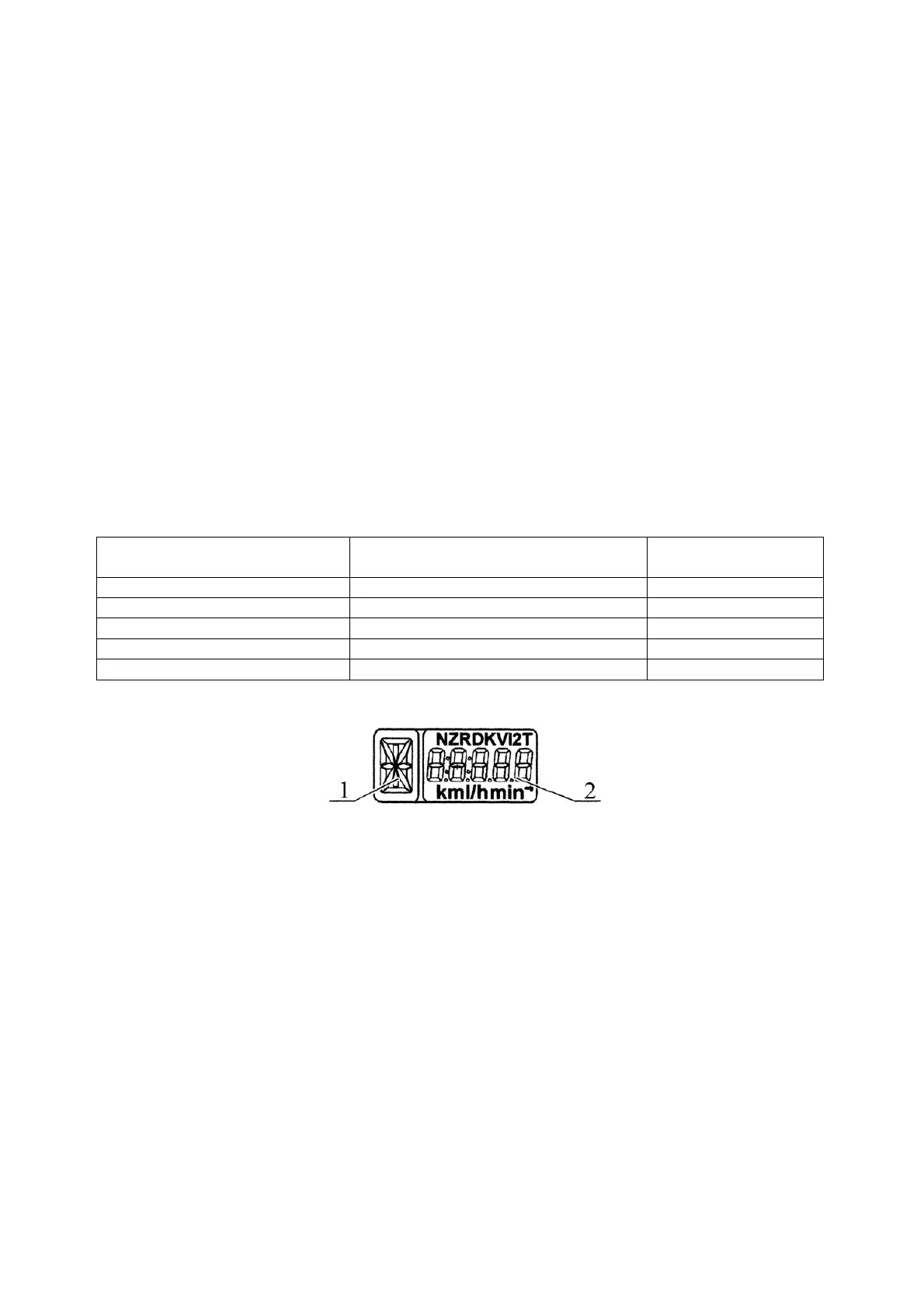
d) Multifunctional display 10 (Figure 2.25.1) is a liquid-crystal display that shows in-
formation in two fields simultaneously (Figure 2.25.2):
1 – digital identification of gear box switch position (digits from 0 to 6) or letter identification of
reducing gear switch position (letters L, M, H, N);
2 – current numeric value of one of tractor system parameters.
Figure 2.25.2 – Information fields of the multifunctional display
Letter “A” is displayed in information field “1” (Figure 2.25.2), because the transmis-
sion control units are missing.
The following parameters are displayed in information field 2 (Figure 2.25.2):
- total elapsed engine time;
- engine operating time over selected period;
- testing workability of speed sensors;
Switching between indication modes of “Total elapsed engine time “, “Engine opera-
tion time over selected period”, switching between messages on faults are effected with
“Mode” button of control panel 7 (Figure 2.23.1). Description of the operation algorithm of
the mode “Testing of workability of speed sensors” is given below.