892-0000010B OM
137
To install the rear ends of lower links 5 (Figure 3.12.11), dismantle crossbar 4, by
means of eyelets 3, pins 2 and cotter pins attach rear ends of lower links to the front ends
of lower links 1, connect limiting buckles 6 to eyelets 3.
ATTENTION: OPERATION OF TRACTORS IS POSSIBLE ONLY WITH EITHER
THE CROSSBAR INSTALLED OR THE REAR ENDS OF THE LOWER LINKS INSTALLED.
SIMULTANEOUS INSTALLATION OF THE CROSSBAR AND THE REAR ENDS OF THE
LOWER LINKS IS NOT ALLOWED!
ATTENTION: IT IS FORBIDDEN TO DRIVE THE BELARUS-892/892.2 TRACTORS
AT A SPEED OVER 15 KM/H WHEN TRAILED MACHINES ARE ATTACHED TO TSU-
1Zh!
IT IS FORBIDDEN TO CONNECT TRAILERS AND SEMI-TRAILERS TO THE
TRAILING APPLIANCE TSU-1Zh.
When the tractor is operating with a tow hitch (TSU-1Zh), the buckles must be fully
locked in the working position. To do this, it is necessary to set the lower links together with
crossbar 4 in a horizontal position and fully locked the buckles in the working position, as
described in clause 3.12.2.1 "Buckles".
Note - The main parameters and characteristics of the TSU-1Zh are presented in
subsection 3.13 "Tow hitches".
3.12.2.4.3 Telescopic buckles and twin crossbar
On order, the BELARUS-892/892.2 tractor can be equipped with a reinforced RLL
with telescopic lower links, which are installed on the axle Ø 35 mm instead of the axle Ø 32
mm (on tractors with a draft control unit, the additional axles are also Ø 35 mm). If necessary,
the length of the telescopic links can be adjusted in steps within ± 80 mm from the middle
position (the resulting link lengths are 805 mm, 885 mm, 965 mm), in this case the load
capacity of the RHL will also change (805 mm - the maximum load capacity, 965 mm – the
minimum load capacity).
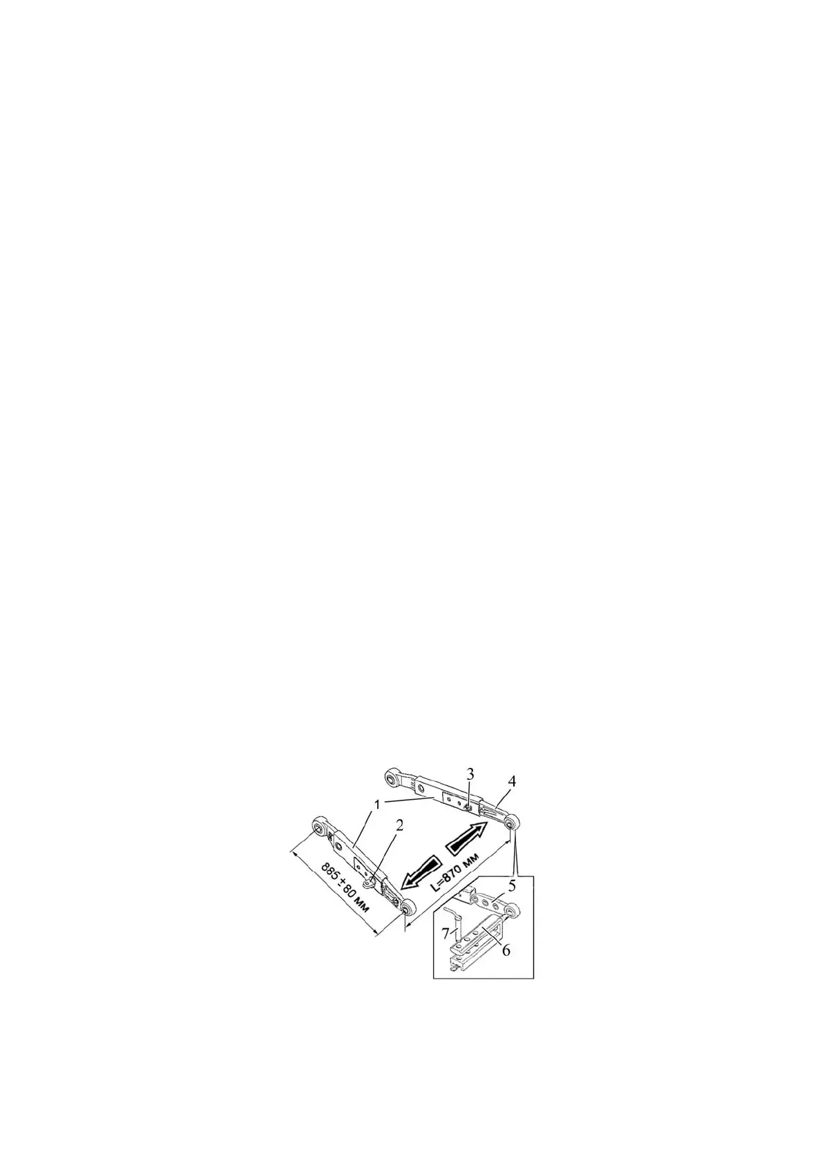
To set the desired length of the lower link, proceed as follows:
- unscrew nut 3 (Figure 3.12.12) and remove eyelet 2;
- move rear end 4 of the telescopic link to the required position, install the eyelet in the corre-
sponding hole and tighten the nut;
- similarly set the required length of the second link.
Eyelets 2 must be installed only in those holes, as it is shown in Figure 3.12.12.
1 - front end of the telescopic link; 2 - eyelet; 3 - nut; 4 - rear end of the telescopic link;
5 - tip of twin crossbar; 6 - twin crossbar; 7 - kingpin.
Figure 3.12.12 – Installation of twin crossbar on telescopic links
Note - Figure 3.12.12 shows the position of telescopic links for a length of 885 mm.