892-0000010B OM
134
Partial locking of the internal buckles in the working position is carried out according to the
same algorithm as the full locking of the buckles in the working position. By rotating buckles 7 in
one direction or another, set the required length of the buckles. After setting the length of the
buckles, it is necessary to check whether the required value of swinging of the implement in each
direction has been ensured. If not, re-adjust the length of the buckles.
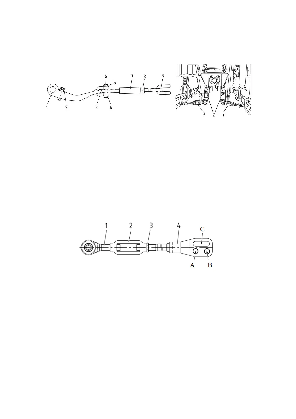
1 – bracket; 2 – bolt; 3 – shackle; 4 – bolt; 5 – nut; 6 – cotter pin; 7 – buckle.
Figure 3.12.6 – Buckle
ATTENTION: AS THE LENGTH OF THE LIFTING ROD IS CHANGED, THE LOCKS
OF THE BUCKLES IN THE TRANSPORT AND WORKING POSITION MUST BE RE-AD-
JUSTED. FAILURE TO DO THIS REQUIREMENT MAY RESULT IN BREAKING OF THE
LIMITING BUCKLES OR OTHER DAMAGES!
3.12.2.2 Lifting rod
Two types of lifting rods can be installed on the tractor: screw and gear type.
On request, one of three configurations of a pair of lifting rods can be installed:
- two geared lifting rods;
- one gear lifting rod (on the right side along the tractor) and one screw lifting rod;
- two screw lifting rods.
The screw lifting rod is shown in Figure 3.12.7.
1 – screw with pivot; 2 – buckle; 3 – locknut; 4 – yoke.
Figure 3.12.7 – Screw lifting rod
Adjust the length of the screw lifting rod in the following sequence:
- unscrew locknut 3;
- rotating buckle 2 clockwise or counterclockwise, change the length of the lifting rod;
- having adjusted the length of the lifting rod, lock the screw connection with locknut
3.
The gear lifting rod is shown in Figure 3.12.8.
The lifting rod length is adjusted by turning handle 5 clockwise or counterclockwise.