892-0000010B OM
98
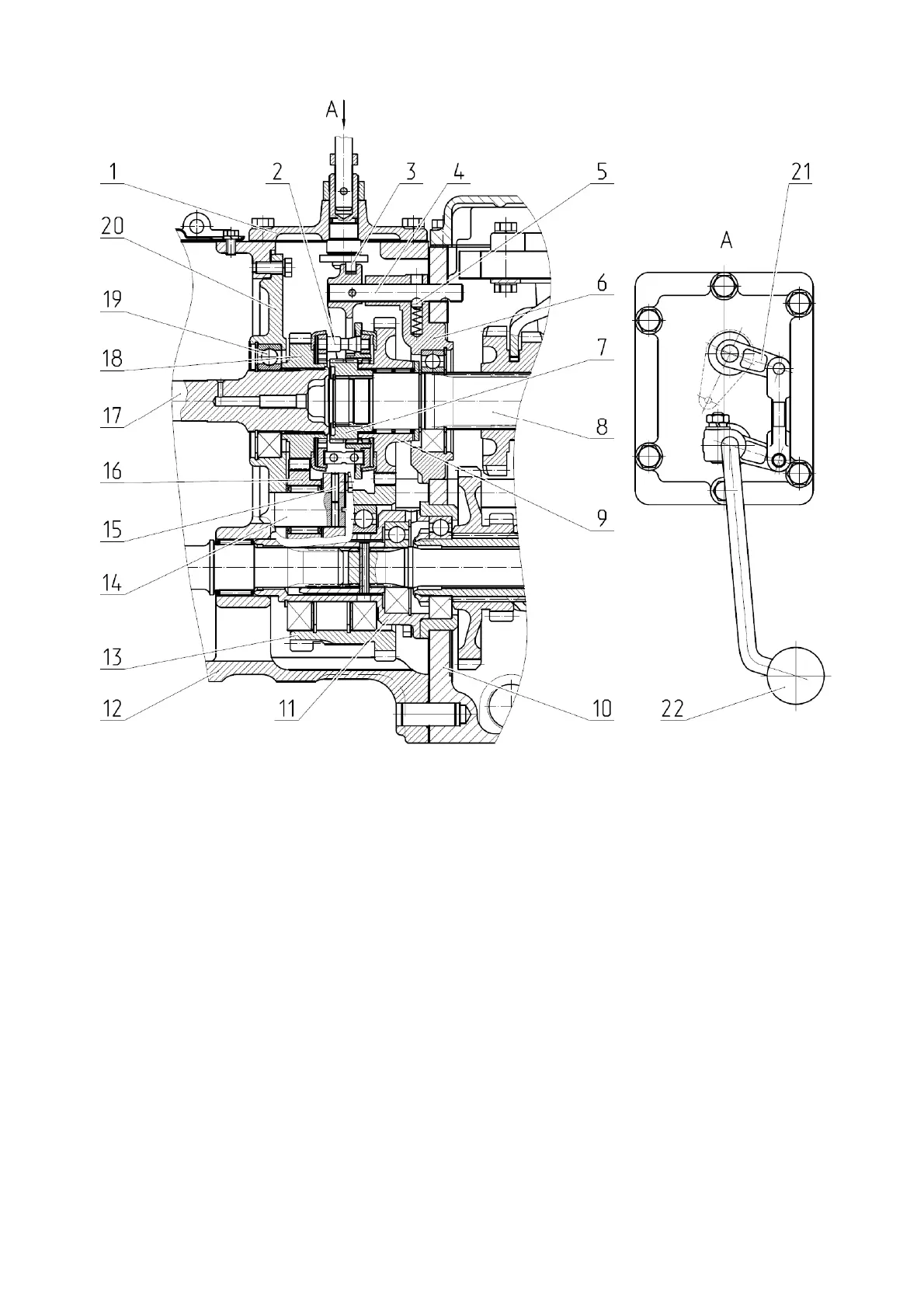
1 – cover of the reverse gear unit; 2 - synchronizer; 3 - lever; 4 - shaft with yoke; 5 - lock
ball; 6 - cage; 7 - bushing; 8 - primary shaft of the gearbox; 9 - driven gear; 10 - gearbox; 11
- front seat; 12 - clutch housing; 13 - intermediate gear; 14 - axle of the planet gear gear; 15
- pin; 16 – planet gear gear; 17 - ball bearing; 18 - power shaft; 19 - drive gear; 20 - cover;
21 – parallelogram mechanism; 22 - reverse gear unit control lever
Figure 3.3.3 Reverse gear unit
3.3.8 Reverse gear unit control
The control of the reverse gear unit consists of shaft with yoke 4 (Figure 3.3.3) and
cover of the reverse gear unit 1.
Shaft 4, whose groove of the yoke is meshed with the hub disk of synchronizer 2, has
the ability to move along the axis in the hole of cage 6 of primary shaft 8. On shaft 4 there
are two transverse holes, into which spring-loaded ball 5 of the latch enters. The holes pro-
vide shaft 4 and the related yoke with it with two fixed positions.
The movement of the shaft with yoke 4 is carried out by lever 3, the movement of
which through parallelogram mechanism 21 of reverse gear unit cover 1 is coordinated with
the movement of reverse gear unit control lever 22. Reverse gear unit cover 1 is installed
on the upper plane of the clutch housing and is bolted to it.