892-0000010B OM
32
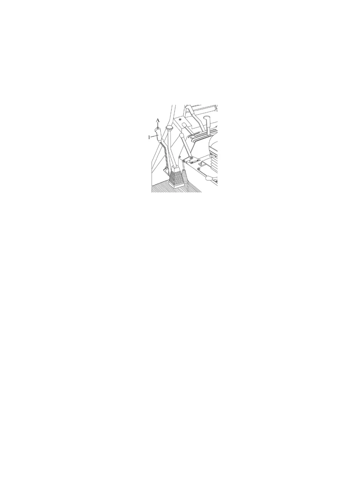
2.9 Parking brake control
Upper position of lever 1 (Figure 2.9.1) – parking brake “On”;
Lower position of lever 1 – parking brake “Off”.
To disengage the parking brake push the control lever button “A” and let lever 1 down
against the stop.
The lever of the parking brake is shown in Figure 2.9.1 in the position “Off”.
1 – lever of the parking brake.
Figure 2.9.1 – Parking brake control
2.10 Engine killing knob, battery switch
As you pull red knob 26 (Figure 2.1.1) fuel delivery to the engine cylinders is stopped and
the engine stops running. When released knob 26 will return to the initial position under the force
of a spring.
As you push button 7 (Figure 2.1.2) batteries will get actuated. Repeated pushing will
deactivate the batteries.
2.11 Manual fuel feed lever, control of engine cooling system shutter
Moving handle 4 (Figure 2.1.2) to the extreme front position ensures max. fuel supply,
moving it to the extreme rear position ensures min. fuel supply corresponding to min. idle speed.
As you start and warm up the cold engine, turn flywheel 2 (Figure 2.1.1) clockwise to
raise the shutter. To reduce coolant temperature put the shutter down by pressing along the
flywheel axis.
2.12 Tractor pedals and FDA drive control
2.12.1 Tractor pedals
2.12.1.1 Pressing pedal 27 (Figure 2.1.1) disengages the clutch.
2.12.1.2 Pressing pedal 23 (Figure 2.1.1) brakes the rear left wheel.
2.12.1.3 Pressing pedal 21 (Figure 2.1.1) brakes the rear right wheel. If a brake valve
is included into the pneumatic actuator configuration, then as you push pedal 22 the brake
valve of the brake pneumatic actuator of trailed implements will operate.
Сonnector of brake pedals 23 is intended for simultaneous braking with the right and left
brakes.
2.12.1.4 Pressing pedal 20 (Figure 2.1.1) increases the engine speed.
2.12.1.5 Pressing pedal 24 (Figure 2.1.1) against the stop will engage the rear axle
differential lock, releasing the pedal will disengage the rear axle DL. The rear axle DL is
used for a short-time locking of rear wheels when overcoming hindrances.
IT IS FORBIDDEN TO RUN THE TRACTOR WITH REAR AXLE DIFFENTIAL LOCK
ENGAGED WHEN MOVING AT THE SPEED ABOVE 13 KM/H.
IT IS FORBIDDEN TO USE PERMANENTLY ENGAGED REAR AXLE DL WHEN TRAV-
ELLING ON ROADS WITH HARD SURFACE.