892-0000010B OM
71
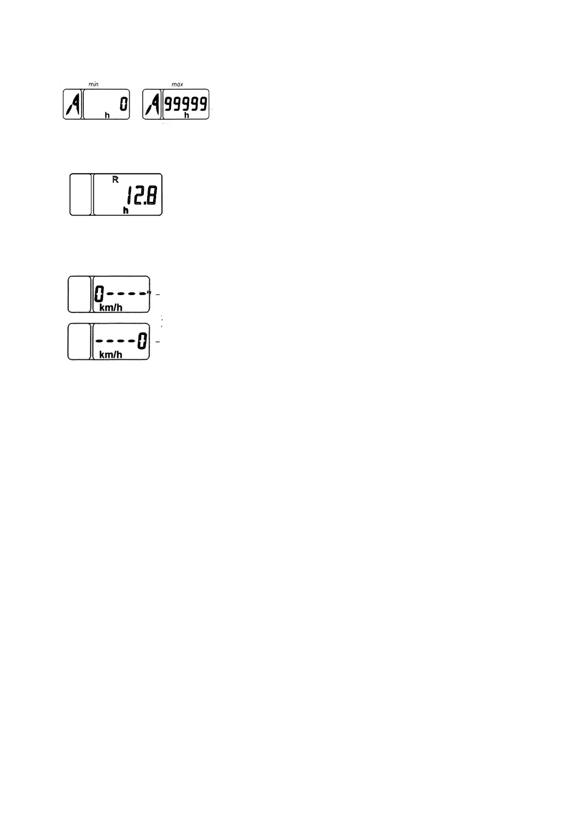
1. Total elapsed engine time, h
The counter accumulates information on the total elapsed
engine time according to a signal from the alternator
phase winding and stores it when the power supply is off.
The range of engine time indications is from 0 to 99999
hours.
2. Engine operation time over selected period
In this mode engine operation time with 1/10-of-an-hour accuracy over a se-
lected period of operation is displayed. If required it is possible to zero the
counter value by way of pressing the “Mode” button and keeping it pressed
for at least 2 sec.
Integrated indicator in the mode of reporting failures
1. Testing workability and connection of speed sensors:
In case there are no signals coming from the speed sen-
sor for 10-12 sec. a message in the form of “0” digit is
displayed on the liquid-crystal display characterizing the
location of the faulty sensor (left or right)
The fault message is displayed on the LCD-display according to priority irrespective
of the information currently displayed. As you push the “Mode” button, the display change
into displaying the operating parameters specified above.
The fault messages are displayed on the LCD-screen every time the device is actu-
ated until the cause is eliminated.
2.25.3 Pilot lamps of the integrated indicator
ATTENTION: PILOT ANNONCIATING LAMPS ARE TURNED ON AND OFF SYN-
CHRONOUSLY WITH CHANGES IN THE STATE OF SYSTEM SENSORS!
а) 5 (Figure 2.25.1) - pilot lamp headlights upper beam lights. It lights up as you turn
on the headlights upper beam;
b) 6, 7 (Figure 2.25.1) - indicators of tractor turn blinkers and trailer turn blinkers. They
operate in a flashing mode as you actuate right or left turn blinkers with underwheel multi-
functional switch 10 (Figure 2.25.1) or as you push the emergency light alarm button;
c) 8 (Figure 2.25.1) - pilot lamp to indicate that the parking brake is enabled. The pilot
lamp “Parking brake” operates in a flashing mode with 1 Hz frequency when the parking
brake sensor goes off;
d) 9 (Figure 2.25.1) - pilot lamp to indicate increased on-board voltage. It lights up
when the tractor on-board supply voltage goes up above 19V and goes out when the voltage
falls below 17V;
In this case the integrated indicator switches off completely, and recovers its opera-
bility when the voltage goes down to the rated value of on-board circuit.
2.25.4 Description of testing the device performance
Each time the power supply is on, performance testing of needle pointers and scale
elements of the PTO indicator is carried out in the integrated indicator. Herewith the indicator
needle pointers move away from initial marks and run over the first digitized scale marks
(over “5” for the speed and over “10” for revolutions), and all segments and indications “540”
and “1000” of PTO scale are activated.
left wheel sensor
right wheel sensor