892-0000010B OM
167
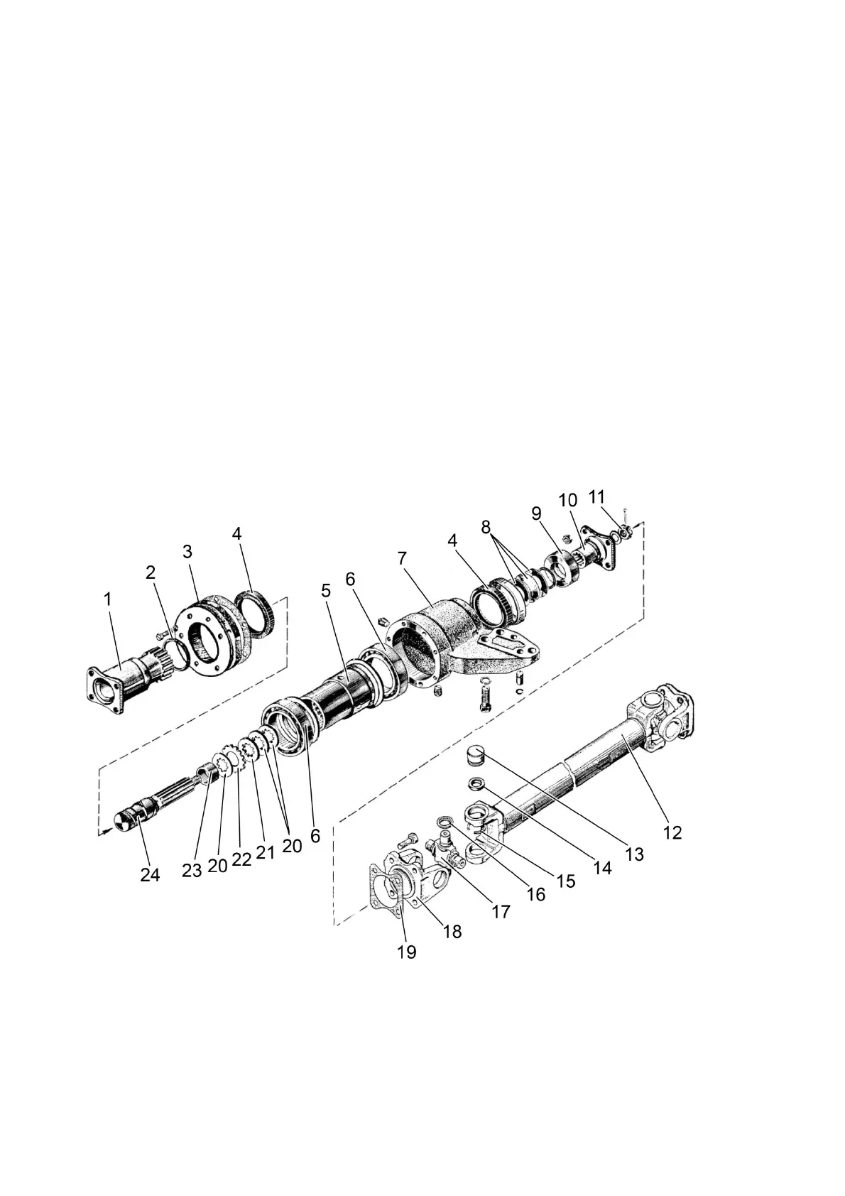
3.16.3 FDA drive
3.16.3.1 Cardan drive
The cardan drive is designed to transmit torque from the transfer box to the front drive axle.
The cardan drive consists of two cardan shafts (intermediate and front) identical in
design and length and an intermediate bearing.
The cardan shaft consists of tube 12 (Figure 3.16.7) and two joints with cross pieces
17 on needle bearings 13. Cages of the needle bearings are locked with lock rings 15, trun-
nions of the cross pieces are provided with end seals 16 and self-moveable gaskets 14. The
cardan shafts are secured by flanges 18 to flanges of the transfer box, intermediate bearing
1, 10 and the front drive axle main pair of gears.
The cardan shaft assembly is dynamically balanced.
The intermediate bearing consists of adjustable multi-disc safety friction coupling and
bearing unit, located in housing 7, which is mounted on pins and is secured by bolts to the
coupling clutch casing from below.
Torque from the intermediate shaft is transferred to flange 10, which is connected by splines
to shaft 24. Pressure discs 20 and drive discs 21 are mounted on shaft 24 and transmit
rotation to bushing 5 through driven discs 22. Flange 1, connected by splines to bushing 5,
transmits torque through the front cardan shaft to the front drive axle. Compression of drive
21 and driven 22 discs is carried out through pressure discs 20 by the force of plate springs
8. The coupling is adjusted to transmit a certain amount of torque by nut 11.
1 – flange; 2 – sealing ring; 3 – gasket body; 4 – gasket; 5 – bushing; 6 - bearing;
7 – housing of intermediate bearing; 8 – plate springs; 9 – washer; 10 – flange; 11 –
nut; 12 – tube of cardan shaft; 13 – needle bearing; 14 – gasket; 15 – lock ring; 16 –
end seal; 17 – cross piece; 18 – flange of cardan shaft; 19 - liner; 20 – pressure disc;
21 – drive disc; 22 – driven disc; 23 – bushing; 24 – shaft.
Figure 3.16.7 Cardan drive of the front drive axle with intermediate bearing