892-0000010B OM
122
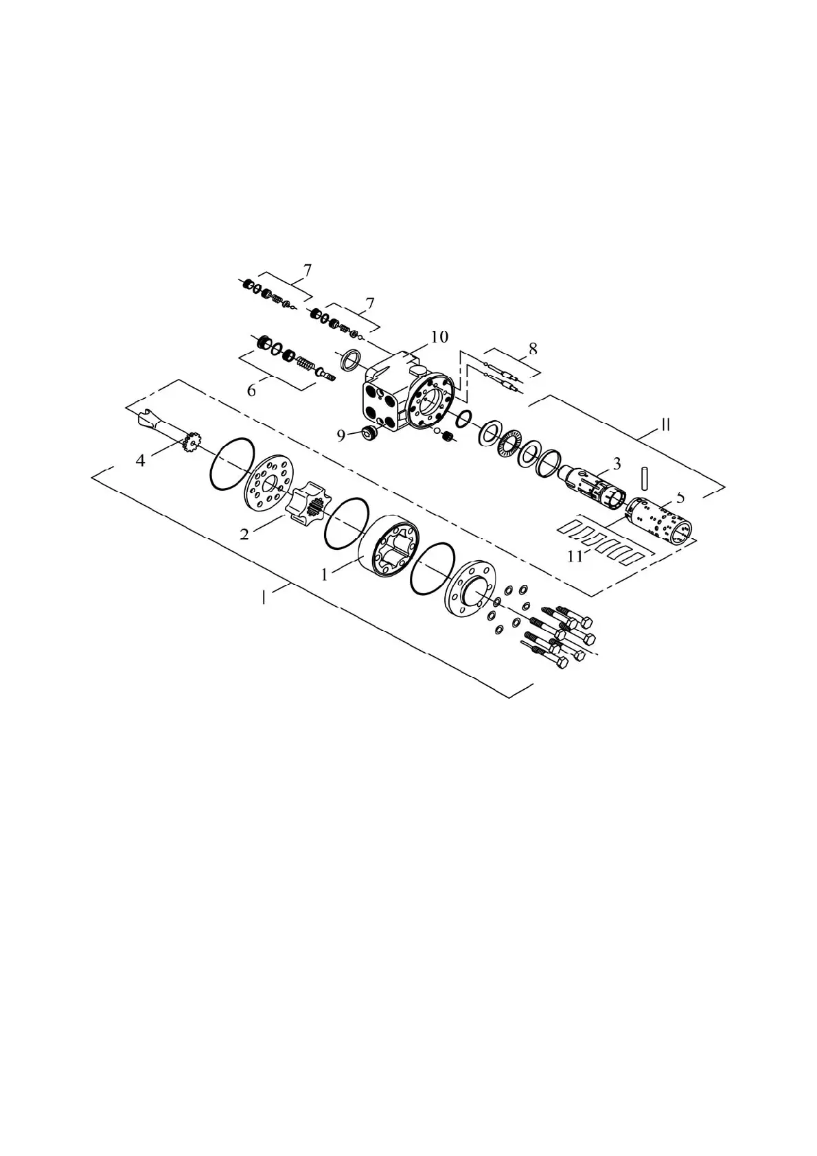
Safety valve 6 protects the pump and HSC hydraulic system from overload, limiting
the maximum pressure in the pressure line within the range from 14 to 15 MPa.
Anti-shock valves 7 (right and left) protect the tubes of the cylinder hydraulic lines
from peak pressures that occur when the steered wheels hit obstacles. The setting pressure
of anti-shock valves is from 20 to 21 MPa.
Anti-vacuum valves 8 (right and left) protect the HSC hydraulic system from vacuum
and cavitation when anti-shock valves are activated and allow oil to be supplied from one
cavity of the hydraulic cylinder to another when the dosing pump is running in the manual
control mode.
1 - stator; 2 - rotor; 3 - spool; 4 - cardan shaft; 5 - sleeve; 6 - safety valve; 7 – anti-shock
valves; 8 - anti-vacuum valves; 9 - check valve; 10 - housing; 11 - leaf springs; I - pumping unit; II -
distributor.
Figure 3.10.3 – Dosing pump
3.10.3 Steering hydraulic cylinder
The differential steering hydraulic cylinder is installed in front of the FDA-822 body
(Figure 3.10.1) or behind the FDA-72 body, and ensures the rotation of the tractor guide
wheels with the help of the steering linkage. The rod of the hydraulic cylinder is connected
to rotary lever 9 of the left wheel gear through conical pin 10, while the body of the hydraulic
cylinder is connected to bracket 13 mounted on the FDA body.
The hydraulic cylinder consists of body 5 (Figure 3.10.4), rod 6, piston 17, front cover
11, captive nut 12. The piston is mounted on the rod with nut 2, which is locked by punching
the belt into the grooves of rod 6. In cover 11, wiper 13, rod seals 14 and 15 and guide rings
16 are installed, eliminating friction of the rod and the cover. Combined seal 3 is installed on
the piston, which eliminates friction between the piston and the body sleeve. In the lugs of
the body and the rod, articulated spherical bearings 1 are installed, which have channels on
the inner ring for the lubrication of friction surfaces. In the Ts63 cylinder, the joints are closed
by bushings 19 and protective rubber boots 18 from contamination.
The joints are lubricated through grease fittings 12 (Figure 3.10.1) in the conical pins
10.