892-0000010B OM
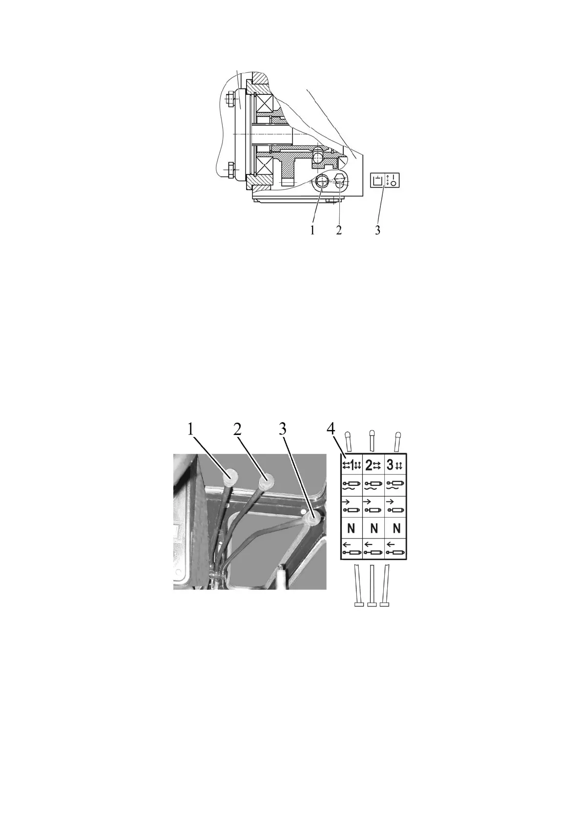
45
1 – HLL pump switching shaft; 2 – bolt; 3 – HLL pump activation diagram.
Figure 2.15.1 – HLL pump control
Note – The Figure 2.15.1 shows the position “HLL pump off”.
ATTENTION: YOY SHOULD TURN THE HLL PUMP ON AND OFF ONLY WITH THE
MIN. IDLE SPEED OF THE ENGINE!
In case failures in HLL occur that lead to oil leakage out of the hydraulic lift linkage,
you must turn the HLL pump off when moving the tractor to repair facilities.
2.15.3 Control of HLL remote cylinders
2.15.3.1 Control of remote hydraulic cylinders with the distributor R80-3/4-222 installed
1, 2, 3, - control handles for hydraulic lift linkage distributor (remote cylinder); 4 - instruc-
tion shield containing control diagram of distributor R80-3/4-222.
Figure 2.15.2 – Control of remote hydraulic cylinders with distributor R80-3/4-222 in-
stalled
Each of the three handles 1, 2, 3 (Figure 2.12.2) of the distributor R80-3/4-222 has
four positions:
"Floating" – uppermost fixed position;
“Forced lowering” – middle upper non-fixed position between “Floating” and “Neutral”
positions. In “Forced lowering” position with the engine running the handle shall be held by
hand, because after released it will return automatically to the “Neutral” position;
“Neutral” – middle bottom fixed position;
“Uplift” – lowermost non-fixed position with automatic return.
HLL pump
Hydraulic system casing