892-0000010B OM
46
In the “Uplift” position with the engine running, the handle will return to the Neutral
position as the pressure for automatic return is reached (cylinder stroke is ended).
Diagram of arrangement and connection of outputs of the distributor R80-3/4-222,
RP70-1221.1S, RP70-1221TS to the external loads on the BELARUS-892/892.2 tractor is
presented in Figure 2.15.3.
Figure 2.15.3 – Diagram of arrangement and connection of outputs of the distributor
R80-3/4-222, RP70-1221.1S, RP70-1221TS to the external loads
2.15.3.2 Control of remote hydraulic cylinders with the distributor RP70-1221.1S in-
stalled
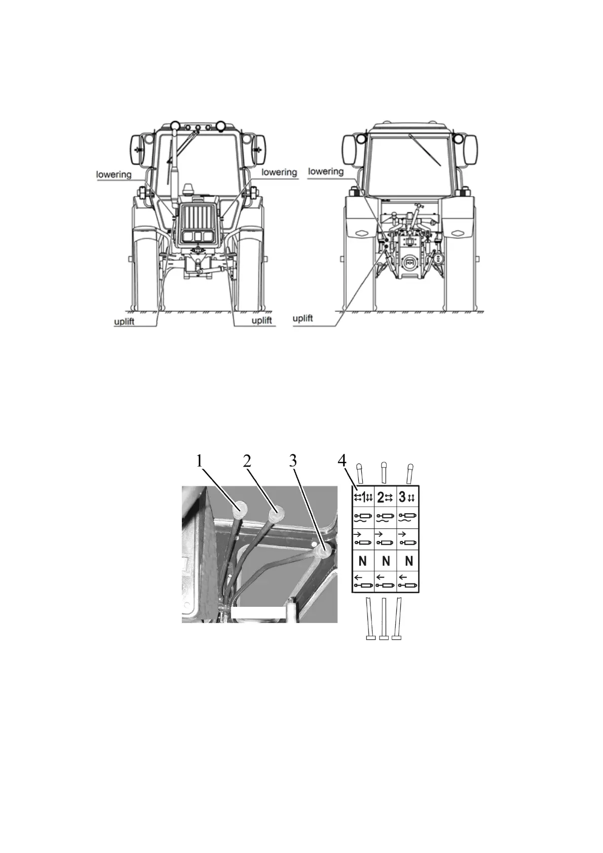
1, 2, 3 - handle to control outputs of the HLL distributor (remote cylinders); 4 - instruction
shield containing control diagram of the
RP70-1221.1S distributor.
Figure 2.15.4 – Control of remote hydraulic cylinders with the distributor RP70-1221.1S
installed
Each of the three handles 1, 2, 3 (Figure 2.15.4) of the RP70-1221.1S distributor has
four positions:
"Floating" – uppermost fixed position;
“Forced lowering” – middle upper non-fixed position between “Floating” and “Neutral”
positions. In “Forced lowering” position with the engine running, the handle shall be held by
hand, because after released it will return automatically to the “Neutral” position;
“Neutral” – bottom fixed middle position;
Lift