892-0000010B OM
29
2.7 Tachospeedometer
2.7.1 General information
The tachospeedometer shows the following operational parameters:
total engine running hours;
tractor motion speed;
rear PTO speed;
speed sensor serviceability;
indication of exceeded voltage in tractor on-board circuit.
The BELARUS-892/892.2 tractors can be equipped with the tachospeedometer AP70.3813
or with an integrated indicator KD 8083.
2.7.2 Tachospeedometer АР70.3813
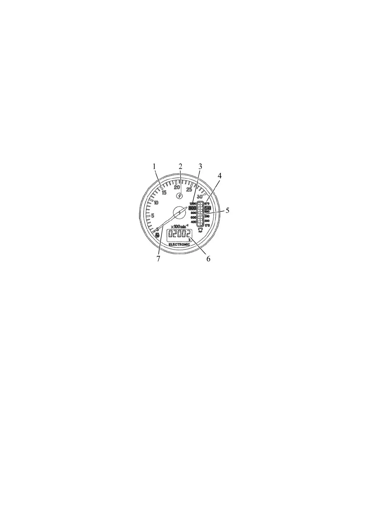
The tachospeedometer АР70.3813 is shown in Figure 2.7.1.
1 – engine speed dial, rpm; 2 – annunciator of increased voltage in tractor on-board circuit
(red color); 3 – indicator of rear PTO speed in the mode of 1000 rpm (light indicator); 4 – indicator of
rear PTO speed in the mode of 540 rpm (light indicator); 5 – rear PTO speed indication display; 6 –
display (LED) indicating total engine running hours and tractor movement speed; 7– needle pointer
of engine crankshaft speed.
Figure 2.7.1 – Tachospeedometer АР70.3813
The operation procedure of the tachospeedometer АР70.3813 is the following:
After you set the starter and instrument switch into position “I” with the tractor stopped, display 6 (Fig-
ure 2.7.1) shows the indication of the engine running hours (h).
After the engine is started, needle indicator 7 will move over dial 1 to indicate the engine crank-
shaft speed. Along of that display 5 will indicate the rear PTO design speed (rpm) – on scale 3 for rear
PTO in the mode of 1000 rpm and on scale 4 for rear PTO in the mode of 540 rpm. The rear PTO turning
speed is calculated according to the signal from the phase winding of the alternator.
As the tractor moves display 6 indicates the design speed of tractor movement (km/h). Hereby
indication of the engine running hours will disappear. Speed readings are taken from the signal of the
sensor installed on the pinion of the final drive of the wheel turning with a less speed. The design speed
is somewhat higher than the actual speed, as it doesn’t take tractor skidding into consideration.
If during the tractor movement display 6 shows Figures “02…07” instead of the speed indi-
cation, and Figure “0” appears after 121 seconds on the right side of display 6 – this means that
the signal from the right speed sensor is missing. It is required to eliminate the fault. If during the
tractor movement display 6 shows Figures “02…07” instead of the speed indication, and Figure “0”
appears after 121 seconds on the left side of display 6 – this means that the signal from the left
speed sensor is missing. It is required to eliminate the fault. Herewith there are no speed indications
on display 6. To bring the speed indications back it is required to eliminate the above failures.
Annunciator 2 of increased voltage in on-board circuit lights up when the supply voltage in the on-board
circuit exceeds 18V and goes out when the voltage goes beyond 16V. When annunciator 2 is on the
tachospeedometer will not function. When the voltage in the tractor on-board circuit exceeds 18V the illumination
lights of the tachospeedometer can break down, if they were turned on. In this case it is required to replace the
illumination lights of the tachospeedometer.
ATTENTION: WHEN THE SUPPLY VOLTAGE IN THE TRACTOR ON-BOARD CIRCUIT GOES
ABOVE 18V THE TACHOSPEEDOMETER WILL TURN OFF COMPLETELY AND WILL RECOVER AS
THE VOLTAGE GOES BEYOND 16V!