892-0000010B OM
84
3.2.3 Clutch control
3.2.3.1 General information
The clutch is controlled as follows:
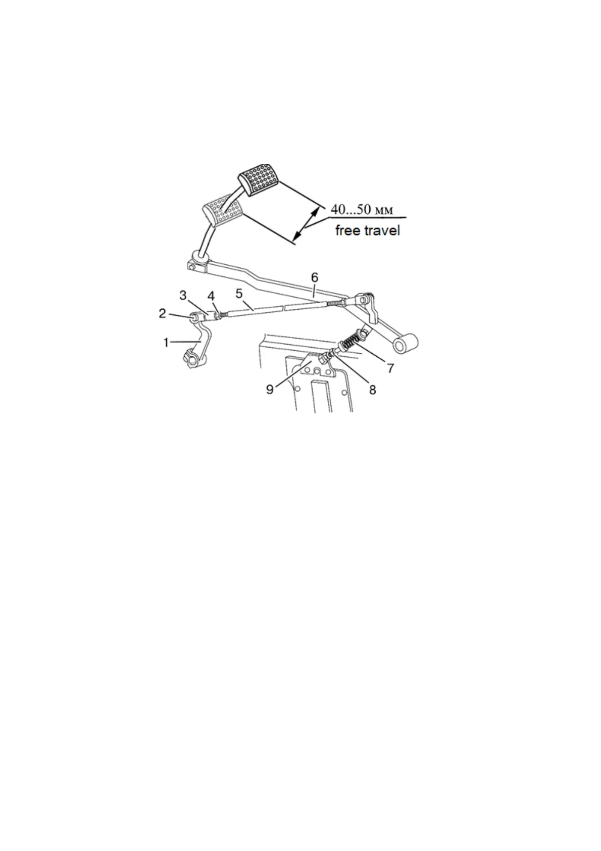
As you push the pad of pedal 6 (Figure 3.2.4), rod 5 moves and turns lever 1, connected
to the clutch shifter through control shaft 18 (Figure 3.2.1). The coupling is then disengaged.
As you release pedal 6 (Figure 3.2.4), the coupling is engaged.
1 – lever; 2 – pin; 3 – yoke; 4 – locknut; 5 – rod; 6 – pedal; 7 – servo unit; 8 – bolt; 9 –
bracket.
Figure 3.2.4 – Clutch control
3.2.3.2 Check/adjustment of clutch pedal free travel
ATTENTION: TOO BIG TRAVEL OF THE PEDAL WILL NOT ALLOW TO DISEN-
GAGE THE COUPLING COMPLETELY AND WILL HINDER GEAR SHIFTING. ABSENCE
OF PEDAL FREE TRAVEL WILL RESULT IN SLIPPING OF CLUTCH PLATES, QUICK
WEAR OF PLATES AND OVERHEATING OF CLUTCH PARTS!
Free travel of clutch pedal measured with the engine killed shall stay within 40 to
50mm. If this value is higher or lower it is required to carry out adjustment of the clutch pedal
free travel.
To adjust the free travel proceed as follows:
- loosen locknut 4 (Figure 3.2.4) of yoke 3, unlock and remove pin 2, detach rod 5
from lever 1;
- proceed with unscrewing bolt 8 until pedal 6 touches the cab floor;
- turn lever 1 contraclockwise until stops. i.e. until the release bearings touch the
clutch levers;
- adjust length of rod 5, turning yoke 3 until holes in the yoke and lever 1 coincide.
Then screw yoke 3 by five revolutions (shorten rod 5);
- tighten locknut 4, connect yoke 3 to lever 1 by means of pin 2.
ATTENTION: MAKE SURE THE CLUTCH PEDAL SECURELY RETURNS UNTIL
STOPS AGAINST THE FLOOR AT THE AREA OF PEDAL FREE TRAVEL. IN THE REVERSE
CASE ADJUST TENSION OF THE SPRING IN SERVO UNIT 7 (FIGURE 3.2.4) BY MEANS
OF BOLT 8 OR CHANGE POSITION OF BRACKET 9, HAVING TURNED IT CONTRACLOCK-
WISE WITH RESPECT TO THE AXIS OF THE MOUNTING BOLT!