892-0000010B OM
42
2.14 Control of power takeoff shafts
2.14.1 General information
On the BELARUS-892/892.2 tractors, the rear power take-off shaft is installed in the
basic configuration.
On request, a lateral semi-continuous PTO can be installed.
Additional information on the rules of operation with power take-off shafts, not in-
cluded in this subsection 2.14, is given in subsection 4.2.7 "Use of PTO".
2.14.2 Rear power take-off shaft control
2.14.2.1 Lever shifting rear PTO from continuous to ground-speed drive
As you move lever 11 (Figure 2.1.2) to the extreme left position (along tractor
movement) a ground-speed drive becomes engaged, and as you move it to the extreme right
position – a continuous drive becomes engaged, while the middle position of the lever is a “neutral”
position.
ATTENTION: ENGAGE GROUND-SPEED DRIVE OF REAR PTO ONLY FROM
NEUTRAL POSITION WITH THE ENGINE RUNNING AT LOW GEAR OF THE FIRST OR
SECOND RANGES OF GB ON THE MOVING TRACTOR. OTHERWISE POWER TRAIN
DAMAGES ARE POSSIBLE! SHIFT PTO GROUND-SPEED DRIVE TO A NEUTRAL PO-
SITION IN A SIMILAR WAY!
ATTENTION: ENGAGE PTO CONTINUOUS DRIVE FROM NEUTRAL POSITION
ONLY WITH ENGINE SHUT DOWN! SHIFT FROM PTO CONTINUOUS DRIVE TO A NEU-
TRAL POSITION IN A SIMILAR WAY!
2.14.2.2 Rear power take-off shaft actuation
Actuation of the rear PTO is possible only when lever 11 (Figure 2.1.2) is moved to
position “ground-speed drive of rear PTO is engaged” or in position “continuous drive of rear
PTO is engaged”. Rear PTO will not operate in "neutral” position.
Rear PTO engaging lever 5 (Figure 2.1.2) has two positions:
- as you move lever 5 from extreme front position to extreme rear position, the rear
PTO gets activated;
- as you move lever 5 from extreme rear position to extreme front position, the rear
PTO becomes deactivated.
It is recommended to engage and disengage the rear PTO when the engine is running.
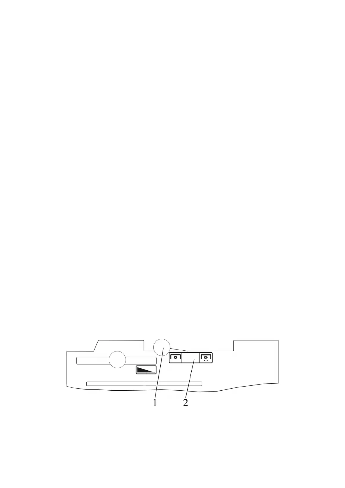
Note – In Figure 2.14.1, rear PTO engaging lever 1 is set into position “rear PTO
disengaged”.
1 – rear PTO engaging lever; 2 – instruction plate for rear PTO control
Figure 2.14.1 – Rear PTO engagement diagram