892-0000010B OM
222
5.10.3 Information about mounting holes of tractor
In the present subsection data on availability of mounting holes of tractor which can
be used by manufacturers of front loaders for loader installation, and also by manufacturer
of tractors for installation of various equipment are set forth. The mounting holes arrange-
ment scheme for BELARUS-892/892.2 tractors is shown in Figure 5.10.2. Parameters of
mounting holes are listed in Table 5.10.2.
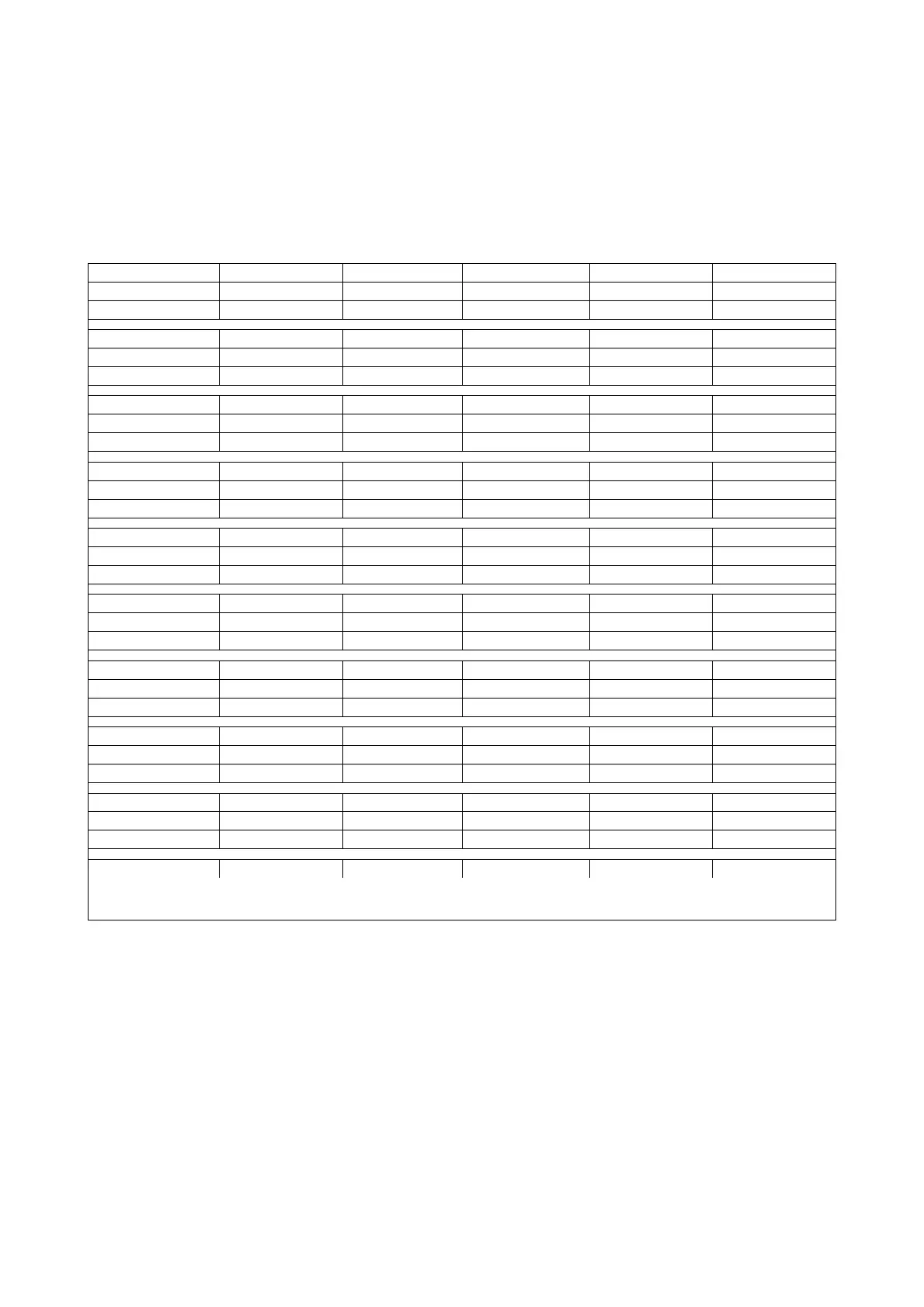
Table 5.10.2 – Parameters of mounting holes of tractor 892/892.2.
Denomination
№ 1 № 2 № 3 № 4 № 5
Diameter**
М16-7H М16-7H М16-7H М16-6H М16-6H
Len
th
28 28 28 28 28
Denomination
№ 6 № 7 № 8 № 9 № 10
Diameter**
М16-6H М16-6H М16-6H 18 18
Len
th
28 28 28 20 20
Denomination
№ 11 № 12 № 13 № 14 № 15
Diameter**
18 18 18 18 18
Len
th
20 20 20 20 20
Denomination
№ 16 № 17 № 18 № 19 № 20
Diameter**
18 М16-6H М16-6H М16-6H М16-6H
Len
th
20 20 20 20 20
Denomination
№ 21 № 22 № 23 № 24 № 25
Diameter**
М16-6H М16-6H М16-6H М16-6H М22х1,5
Len
th
20 20 20 20 54
Denomination
№ 26 № 27 № 28 № 29 № 30
Diameter**
М22х1,5 М22х1,5 М22х1,5 17 17
Len
th
54 54 54 174 174
Denomination
№ 31 № 32 № 33 № 34 № 35
Diameter**
17 17 17 17 18
Len
th
174 174 174 174 14
Denomination
№ 36 № 37 № 38 № 39 № 40
Diameter**
18 18 18 18 18
Len
th
14 14 14 14 14
Denomination
№ 41 № 42 № 43 № 44 № 45
Diameter**
18 18 18 18 -
Len
th
14 14 14 14 -
Len
th - - - - -
_________________________________________________________
* Blind hole.
** Threadin
arameters are indicated for holes with threads.
NOTES:
Sizes in Table 5.10.2 are given in mm.
Holes 1…20 are right and left.
In course of mounted components installation ensure safety of bushings in holes 6A and 7A.
It is not recommended to use holes with bushings for coupling.
Use holes 35…43 only for fixture of non load-bearing construction elements.
ATTENTION: IT IS NOT RECOMMENDED TO USE SIDE HOLES WITH BUSHINGS!
MOUNTED LOADER COMPONENTS SHOULD NOT CAUSE BUSHING DESTRUCTION!