892-0000010B OM
121
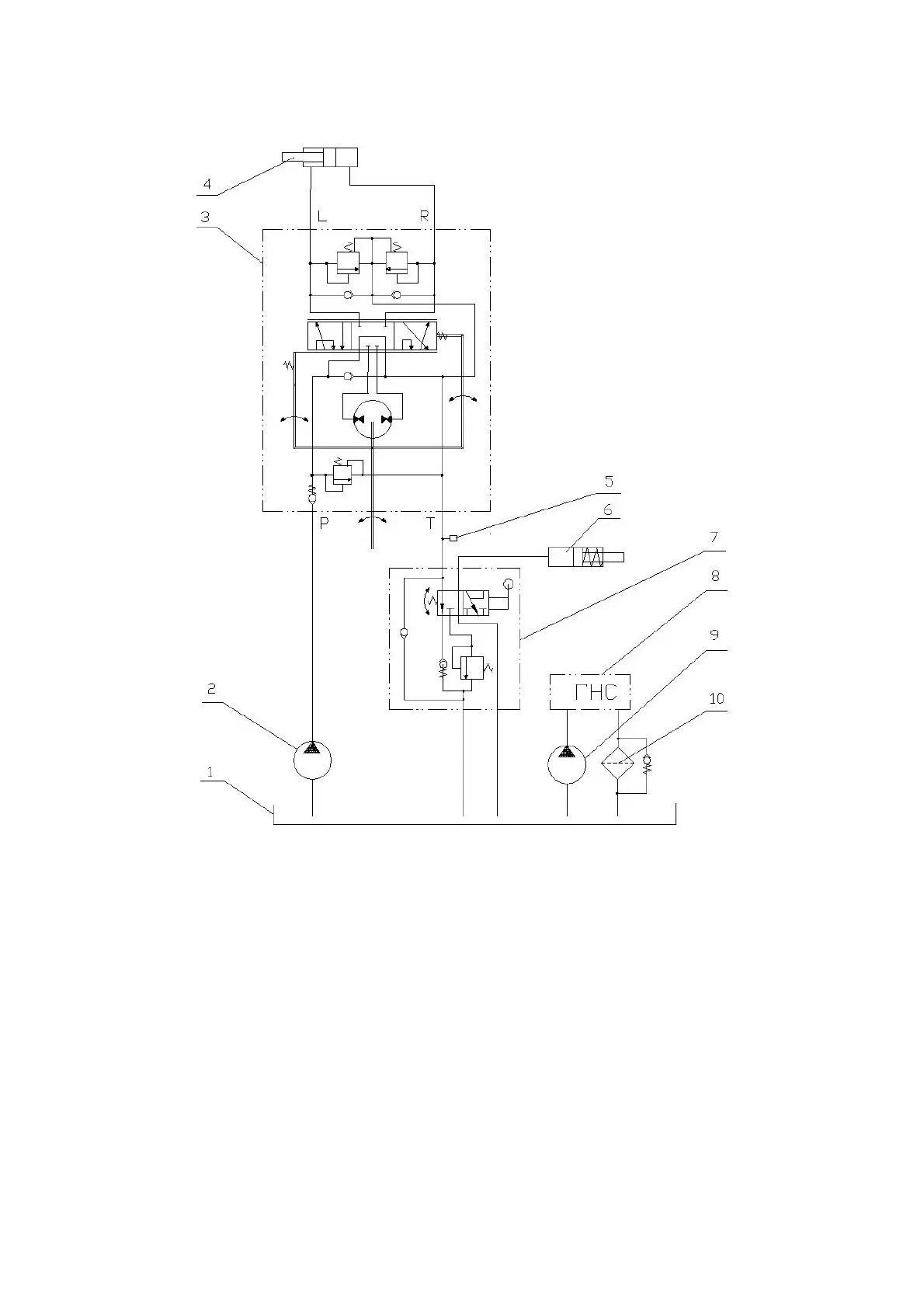
The hydraulic circuit diagram of the HSC of the BELARUS-892/892.2 tractors is shown in
Figure 3.10.2.
1 - combined oil tank for HLL and HSC; 2 - HSC feed pump; 3 - dosing pump; 4 -
steering hydraulic cylinder; 5 – sensor of emergency oil pressure in the HSC; 6 - differential
lock clutch; 7 - valve for locking the rear axle differential (with pedal control); 8 - HLL hydrau-
lic system; 9 - HLL pump; 10 - drain filter; Р - pressure hydraulic line; T - drain hydraulic line;
L - hydraulic line of the left turn; R - hydraulic line of the right turn.
Figure 3.10.2 Hydraulic circuit diagram of the HSC of the BELARUS-892/892.2 trac-
tors with differential lock valve.
3.10.2 Dosing pump
The dosing pump is gerotor-type with an "open center" and no reaction on the steer-
ing wheel. It includes housing 10 (Figure 3.10.3), pumping unit I, distributor II, two anti-shock
valves 7, safety valve 6, two anti-vacuum valves 8 and check valve 9.
The gerotor pumping unit I consists of stator 1, attached to housing 10, and rotating
rotor 2 connected to spool 3 through cardan shaft 4.
Distributor II consists of sleeve 5, a set of leaf springs 11 and spool 3 connected to
the end of the steering column drive shaft with its splines.
The check valve ensures the operation of the dosing pump in a manual control mode
as a manual pump when the feed pump is not running.