892-0000010B OM
120
The drain hydraulic line "T" has blocking valve 2 installed, which is intended to control
the hydraulic clutch for locking the differential of the tractor rear axle.
The connection between the steering wheel and the guide wheels is carried out hydrau-
lically by means of oil pipelines and high-pressure hoses connecting dosing pump 4, mounted
on the steering column, and differential hydraulic cylinder 11, mounted on the front drive axle
housing.
As you turn the steering left or right, the centering leaf springs are compressed in meter-
ing pump 4, and the distribution grooves of the spool are rotated (the spool is connected to the
steering wheel shaft through splines) relative to the grooves of the sleeve, as a result of which
oil from supply pump 7 flows under pressure through the dosing gerotor assembly of the dosing
pump into the corresponding cavity "R" or "L" of steering hydraulic cylinder 11 in a volume pro-
portional to the amount of steering wheel turn, and oil from the other cavity of hydraulic cylinder
11 enters the drain hydraulic line "T" through the channels in the spool and sleeve, and merges
into the oil tank.
As you stop turning the steering wheel, the sleeve returns to a neutral position relative
to the spool under the influence of the centering leaf springs of the metering pump, the
cylinder hydraulic lines “L” and “R” are locked, and oil flows from the pressure hydraulic line
“P” to drain "T" through the channels in the spool and sleeve, which ensures pressure relief
in the pressure hydraulic line "P" and unloading of feed pump 7.
The locked volume of oil in the cavities of hydraulic cylinder 11 ensures the stability
of the direction of movement of the tractor when the steered wheels hit unevenness of road
or soil.
Under normal operating conditions, when supply pump 7 provides the oil pressure neces-
sary to turn the guide wheels, the maximum effort applied by the operator to turn the steering
wheel does not exceed 30 N.
If the oil flow from the feed pump is too small or is missing (for example, if the diesel engine,
the feed pump are faulty, if the pressure oil line is destroyed or there is no oil in the oil tank), then
when the steering wheel is turned, dosing pump 4 performs the function of a manual pump, pump-
ing oil from one cavity of hydraulic cylinder 11 into another, which ensures turning of the guide
wheels. The effort on the steering wheel applied by the operator to create the necessary oil pres-
sure in hydraulic cylinder 11 during manual control, increases significantly, in some cases up to
600 N.
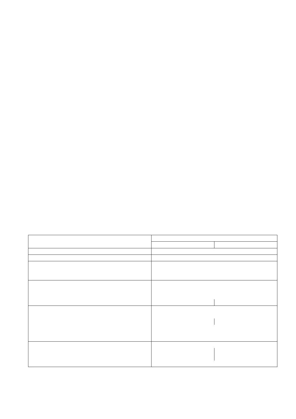
Table 3.10.1 – Technical specification of HSC
Name of HSC parameter
Parameter value
BELARUS-892 BELARUS-892.2
Effort on the steering wheel, N, no more 30
Play of the steering wheel, degree, no more 25
Speed of "sliding" of the steering wheel in the
extreme positions when an effort of 100 N is ap-
plied to the steering wheel
3 rpm, no more
Feed pump:
-type gear-type
-direction of rotation left
-displacement, cm
3
/rev 10 14
Dosing pump:
-type gerotor-type, with open center, without response
-displacement, cm
3
/rev 100 160
-safety valve setting pressure, MPa 14
+1
-anti-shock valve setting pressure, MPa
20
+2
Steering gear: hydraulic cylinder and steering linkage
-piston diameter, mm 50 63
-rod diameter, mm 25 30
-rod stroke, mm 200