892-0000010B OM
85
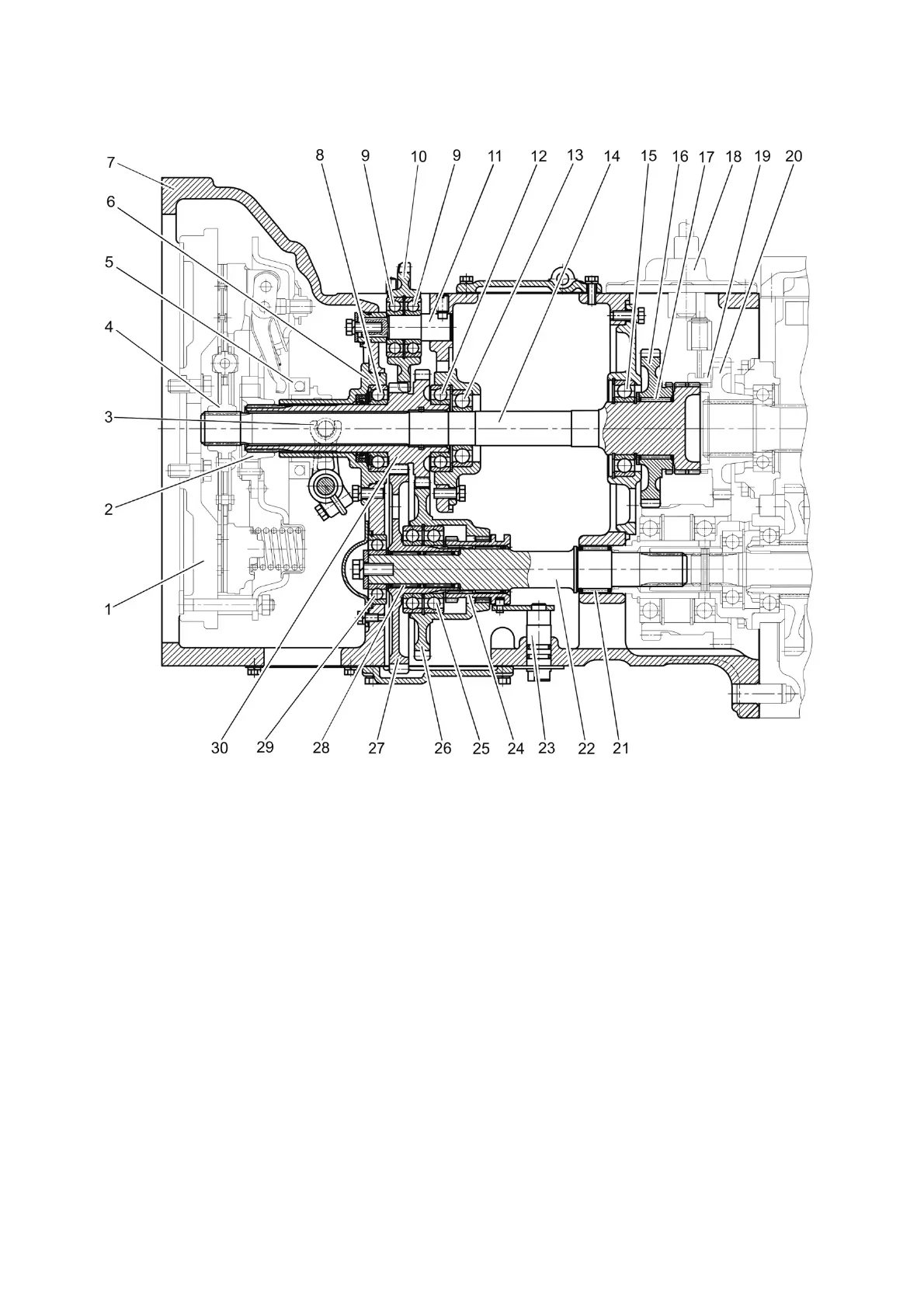
3.2.4 Clutch housing
The clutch housing of the BELARUS-892/892.2 tractors is shown in Figure 3.2.5.
1 - flywheel; 2 - floating bushing; 3 - yoke; 4 - hub; 5 - release bearing; 6 – shifter
bracket; 7 - clutch housing; 8, 9, 12, 13, 15, 25, 29 - bearing; 10 – HLL pump drive gear; 11 -
axle; 14 - power shaft; 16 - drive gear of the reducing gear unit; 17 - rollers; 18 – reducing
gear unit control mechanism; 19 – toothed clutch; 20 - driven gear of the gear unit; 21, 28 -
needle bearing with outer race; 22 - driven shaft of the PTO drive; 23 - control shaft; 24 -
toothed clutch; 26 – driven gear of the PTO drive (1000 rpm mode); 27 – driven gear of the
PTO drive (540 rpm mode); 30 - driving pinion-shaft of the PTO drive.
Figure 3.2.5 – Clutch housing with increasing gear unit (or with reducing mechanical gear
unit)
Clutch housing 7 (Figure 3.2.5) can be conditionally divided into two parts: a dry com-
partment and a gear part.
In the dry compartment of the clutch housing there is a clutch mounted on flywheel 1
of the engine. On shifter bracket 6, also located in the dry compartment, a shifter with release
bearing 5 is installed, the shifter trunnions enter the eye of clutch release yokes 3. A grease
fitting is screwed into one of the shifter trunnions, intended to lubricate the release bearing.
The gear part includes a continuous two-speed rear PTO drive, HLL pump drive and
an increasing gear unit.