892-0000010B OM
81
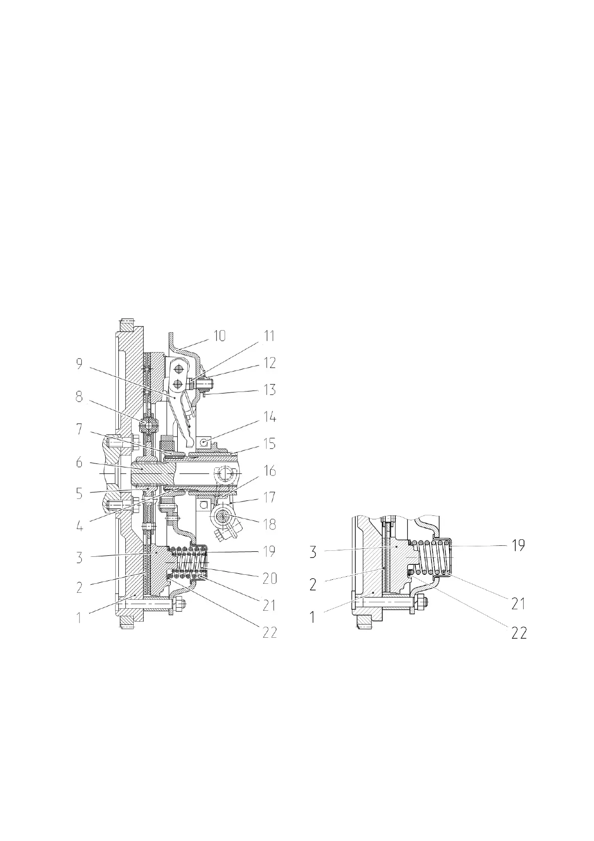
3.2 Coupling
3.2.1 Coupling clutch
On flywheel 1 (Figure 3.2.1) of the engine, a dry single-plate spring-loaded clutch is installed.
The leading part of the clutch is flywheel 1 and pressure plate 3. The driven part of the clutch
includes driven plate 2 (basic configuration - asbestos-free linings, on request - ceramic-metal seg-
ments) with torsional vibration damper 8, mounted on power shaft 6.
On the BELARUS-892/892.2 tractors, the necessary pressing force of the friction surfaces of
the driving and driven parts is provided by nine main springs 21 and six additional springs 20 (Figure
3.2.1 a).
If the tractor is equipped with driven plates having ceramic-metal segments, the required press-
ing force of the friction surfaces of the driving and driven parts is provided only by nine main springs
21 (Figure 3.2.1b).
Elastic parts are installed between floating bushing 7 connected to PTO drive shaft 4 and back-
ing plate 10. The coupling is engaged and disengaged by shifter 16 with release bearing 14 moving
along bracket 15. Yoke 17 of the shifter with shaft 18 are connected to the clutch pedal by a link.
Release bearing 14 is lubricated through a grease fitting screwed into the shifter pin.
а) Tractor clutch with asbestos-free linings of
driven plates, with additional springs in the clutch
cover
b) Tractor clutch with metal-ceramic segments of
driven plates, without additional springs in the clutch
cover (for the rest see Figure а)
1 - flywheel; 2 - driven plate; 3 - pressure plate; 4 - PTO drive shaft; 5 - hub; 6 - power
shaft; 7 - floating bushing; 8 - torsional vibration damper; 9 - release lever; 10 - backing plate;
11 - yoke; 12 - nut; 13 - locking plate; 14 - release bearing; 15 - shifter bracket; 16 - shifter; 17 -
release yoke; 18 - control shaft; 19 - retainer; 20 - pressure spring; 21 - pressure spring; 22 -
insulating washer.
Figure 3.2.1 – Coupling clutch