892-0000010B OM
187
4.2.11 Front wheel track formation
4.2.11.1 General information
On BELARUS-892 tractor is mounted FDA with bevel wheel gear groups (72-2300020-
А-04).
On BELARUS-892.2 tractor is mounted FDA with spur planetary wheel gear groups
(822-2300020-02 – with long beam, 822-2300020-04 – with short beam).
Rules for front wheels track formation of the BELARUS-892 tractor with FDA with bevel
wheel gear groups are given in clause 4.2.11.2.
Information of possible variants of front wheels track installation of the BELARUS-892.2
tractor with FDA with spur planetary wheel gear groups are given in clause 4.2.11.3.
4.2.11.2 Front wheels track formation of the tractors equipped with FDA with bevel
wheel gear groups
Wheel track of tractors, equipped with FDA with bevel wheel gear groups can be
changed step-by-step depending on the lengths of extension of wheel gear groups (dimen-
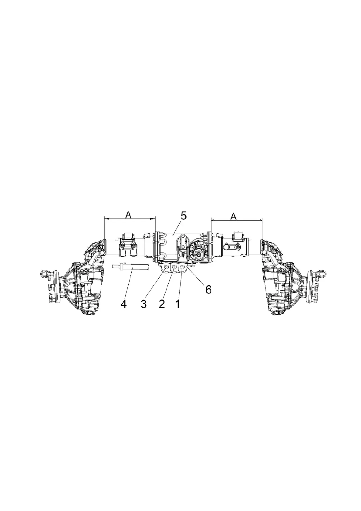
sion А in figure 4.2.7) and, accordingly, on the hole of HSC cylinder fastening (holes 1, 2, 3,
as shown in figure 4.2.7), and can make 1410, 1520, 1630 mm, and with replacing the
wheels from one sideboard to the other 1710, 1820, 1930 mm (with front tyres 13.6-20
mounted).
1, 2, 3 – holes for cylinder fastening; 4 – cylinder; 5 – FDA; 6 – bracket.
Figure 4.2.7 – Rules of changing the front wheel track on tractor equipped with FDA
72-2300020-А-04
To set the necessary track by means of extending the wheel gear groups, do the fol-
lowing operations:
- brake the tractor using the parking brake. Put wheel chocks at the front and back of
rear wheels;
- jack up the front part of the tractor (or the front wheels, one by one) to provide
clearance between the wheels and the ground;
- release four bolts fastening the cover of adjusting screw and remove cover 2 (Figure
4.2.8);
- unscrew two nuts and remove two wedges 1;
- loosen the tightening of nuts 3 at the ends of steering link tube 5;
- remove split pin 7, and then remove lock-pin 6. If distance “H” is larger than 70 mm,
change the position of lock finder 6 (position II);
- detach cylinder 4 from bracket 6 (Figure 4.2.7);
- by rotating adjusting screw 4 (Figure 4.2.8) with a wrench, move the body of the
bevel pair with a hub drive unit to reach the necessary distance “A”. At the same time, by