892-0000010B OM
116
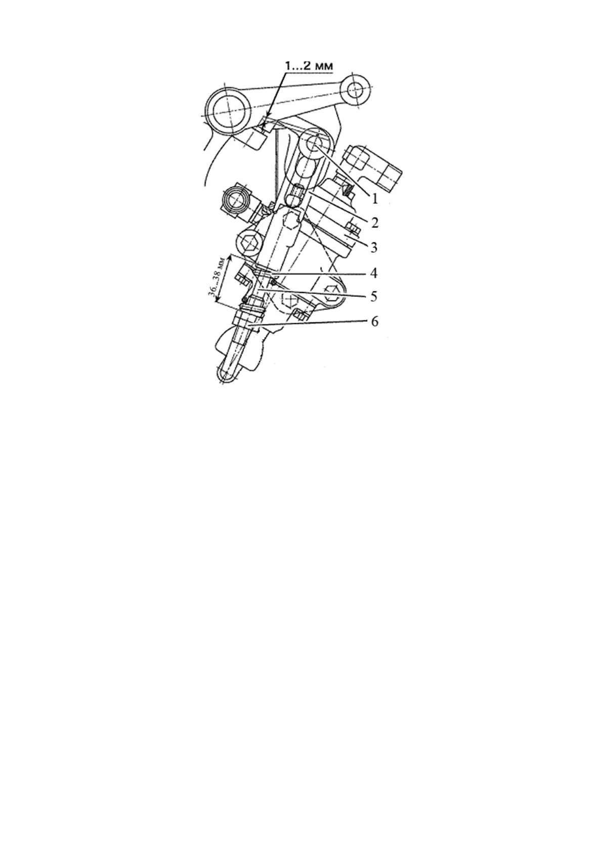
1 - pin; 2 - tip; 3 - brake valve; 4 - spring; 5 - rod; 6 - nut.
Figure 3.8.2 - Adjustment of the drive of the pneumatics brake valve
Checking and, if necessary, adjusting the drive of the pneumatic system brake valve
must be carried out as follows:
1. Attach a pressure gauge with a scale of at least 1 MPa to the connecting head
(with a black cover) of the tractor pneumatic drive.
2. Start the engine and fill the tank with air to a pressure of 0.77 to 0.8 MPa according
to the air pressure indicator in the pneumatic system located on the dashboard. Stop the
engine.
3. The air pressure according to the pressure gauge attached to the connecting head
must not be lower than 0.77 MPa. If it is lower than specified, perform the following opera-
tions:
- check for a gap of 1 to 2 mm between pin 1 and the upper edges of the grooves in
the levers, as shown in Figure 3.8.2. If there is no gap, remove cotter and remove pin 1, and
adjust the length of rod 5 by turning tip 2;
- check and, if necessary, adjust the preload of spring 4 to the size from 36 to 38 mm
(as shown in Figure 3.8.2) by turning nuts 6 and lock them.
- perform operations No.1 and No.2.
4. If, after the adjustments made, the air pressure according to the pressure gauge
attached to the connecting head has not reached 0.77 MPa, replace brake valve 3.
ATTENTION: WITH A FUNCTIONAL BRAKE VALVE 3 (FIGURE 3.8.2) AND A COR-
RECTLY ADJUSTED BRAKE VALVE DRIVE, THE PRESSURE, WHEN CHECKED WITH
THE GAUGE CONNECTED TO THE CONNECTING HEAD (WITH A BLACK COVER),
MUST FALL TO ZERO AS YOU MOVE THE INTERLOCKED PEDALS TO A COMPLETE
STROKE OR FULLY ENGAGE THE PARKING BRAKE!