892-0000010B OM
131
When working with some implements, it is necessary to ensure that the implements
swings in each direction by at least 125 mm or by another value, in accordance with the machine
(implement) operating instructions. To do this, it is necessary to partially lock the buckles in the
working position.
Partial locking of the buckles in the working position must be carried out as follows:
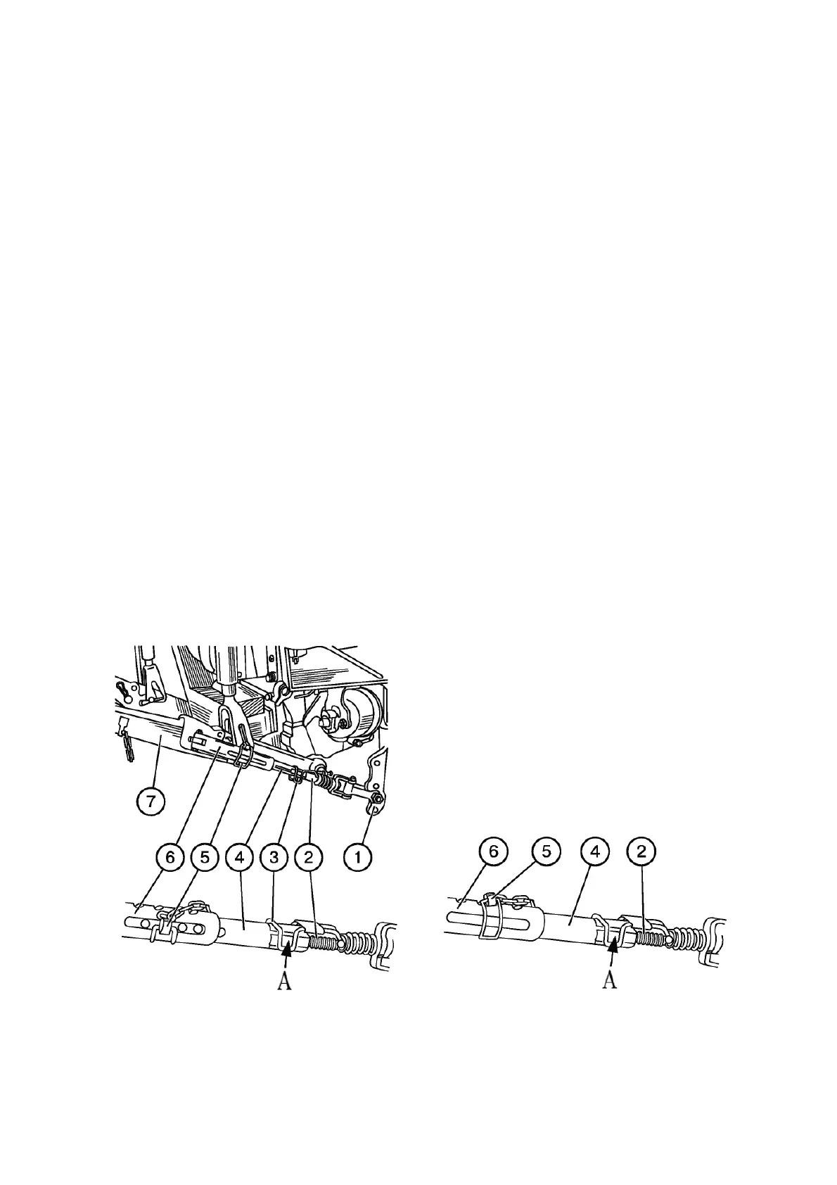
- turning screw 2 (Figure 3.12.4), set handle 3 in the middle of flat “A”;
- remove cotter key 5 from the buckle;
- attach the machine (implement) to lower links 7 and lift it up to take it off the ground;
- place the machine (implement) symmetrically to the longitudinal axis of the tractor;
- aligning the holes of inner pipe 4 with the groove of outer pipe 6, insert cotter key 5 into
the hole of inner pipe 4 closest to the middle of the groove;
- adjust the position of cotter key 5 by turning screw 2 using handle 3 so that the cotter
key is placed in the middle of the groove of outer pipe 6.
ATTENTION: INSTALL COTTER KEY 5 (FIGURE 3.12.4) SO THAT IT IS LOCATED IN
THE MIDDLE OF THE GROOVE OR WITH A MINIMUM OFFSET TO THE SIDE OF THE TRAC-
TOR. OTHERWISE THE BUCKLES MAY BE DAMAGED!
During inter-row cultivation, sowing and some other types of work, the RLL lower links
must be completely locked from transverse movements in order to avoid damage to plants when
the implement swings. To do this, it is necessary to perform a full locking of the buckles in the
working position.
Full locking of the buckles in the working position must be carried out as follows:
- turning screw 2 (Figure 3.12.4), set handle 3 in the middle of flat “A”;
- remove cotter key 5 from the buckle;
- attach the machine (implement) to lower links 7 and lift it up to take it off the ground;
- place the machine (implement) symmetrically to the longitudinal axis of the tractor;
- turn inner pipe 4 manually so that its holes are in the upper part of the pipe;
- align one of the holes of inner pipe 4 with the closest hole of outer pipe 6 and insert
cotter key 5 into them;
- check the value of the side swing of the machine (implement), which should not exceed
20 mm in each direction;
- if necessary, adjust the value of the side swing of the machine (implement) by turning
screw 2.
a) Partial locking of telescopic buckles b) Full locking of telescopic buckles
1 – bracket; 2 – screw; 3 – handle; 4 – inner pipe; 5 – cotter key; 6 – outer pipe; 7 – lower
link.
Figure 3.12.4 – Partial and complete locking of telescopic buckles