892-0000010B OM
219
For installation of the complete set of the loading equipment bores on a front beam,
frame rail and a tractor clutch coupling case are used. For the purpose of unloading of a
semi-frame and a tractor clutch coupling case use adjustable bars or other constructive el-
ements connected to rear semi-axles tubes of rear axle transferring a part of push force to
tractor rear axle. For rigidity maintenance it is desirable, that the right and left parts of loader
mounting frame have been rigidly connected among themselves.
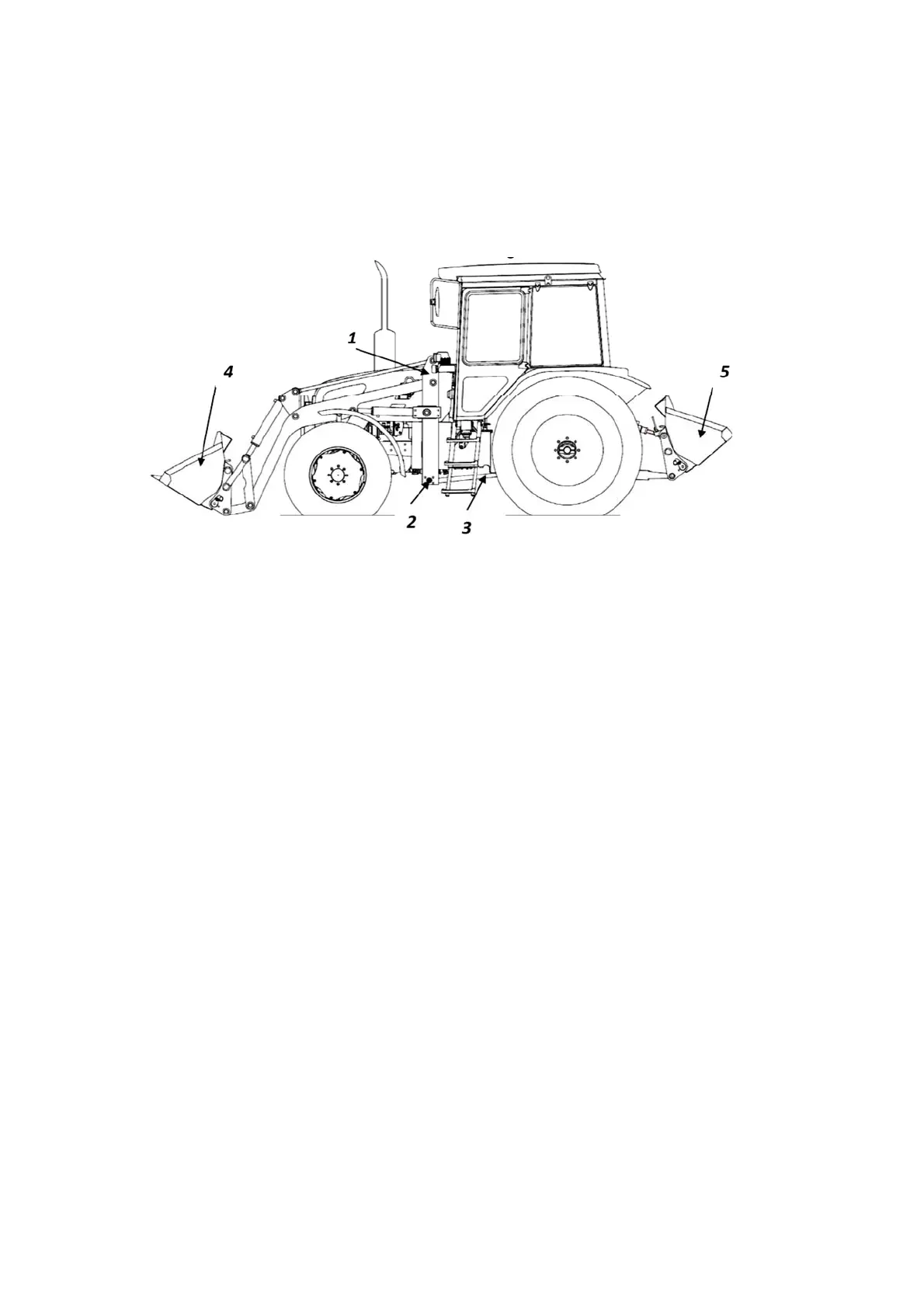
Loader installation scheme is shown in Figure 5.10.1.
1 –loading equipment kit for tractor; 2 – crossed linkage of loader frame; 3 – tapped
rod; 4 – loader bucket; 5 – rear ballast weight.
Figure 5.10.1 – Loader installation scheme
To ensure sufficient drawbar power generated by tractor rear wheels, it is necessary
to create adequate load on rear axle equal or exceeding 60 % of tractor operational weight
with regard to installed loader weight.
Right proportion of loads on axles can be achieved by rear axle ballasting by means
of loads, solution, filled in wheel tires, rear counterweight (hook-on bucket with ballast load),
attached to rear lift linkage.
ATTENTION: IN LOADER OPERATION MANUAL DESIGNED FOR CONSUMER,
LOADER MOUNTING ORDER SHALL BE SET FORTH WITH PICTURES INCLUSIVE OF
DATA ON SHIFTING AND DISMOUNTING OF TRACTOR COMPONENTS.
In a loader design safety and interlocking devices (fast coupling clutches, slowing-
down valves, overload limiter and another), should be provided excluding conflicting motions
of gears, overloads and breakages in operation on excess of admissible pressure values in
hydraulic system, nominal load capacity or drawbar power.
In mode of ground cutting it is necessary to provide protection of tractor and loader
chassis and from overload. Loader working attachment overturning (bucket and etc.), due
to special valve actuation integrated in loader system.
In order to avoid breakages for the purpose of loader lowering speed limitation, the
loader should be equipped with slowing-down valves in lifting cavity of loader hydraulic cyl-
inders.
Loader design is to provide possibility of fixing working attachments in transport po-
sition.
To exclude contact and/or tractor and loader damages the minimum
distances between
fixed members of tractor and loader components attached to it should be not less than 0.1 m, and
in case of moving member – not less than 0.15 m.
On a loader should bear marks “Maximum speed limitation”, and also necessary
warning labels, for example: to "Fix". On loader operating equipment limit values of load-
carrying capacity
should be specified on the fore.