Chapter 2 Specifications and System Configuration
2-77
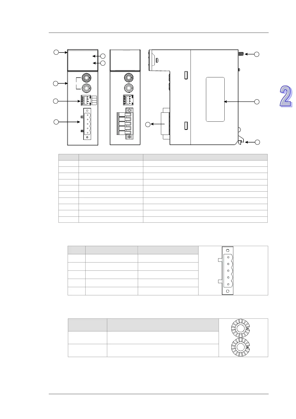
AH10COPM-5A
7
10
9
8
DR 2
RUN
ERROR
x16
x16
0
1
Node Address
DR 1
DR 0
IN 0
GND
CAN-
SHLD
CAN+
1
2
3
4
6
5
10COPM
Operating status of the module
Error status of the module
1. CANopen communication connector
A CANopen connector is connected to a CANopen network. Please wire AH10COPM-5A by using the
connector attached to AH10COPM-5A.
Pin Signal Description
5 - Reserved
4 CAN+ CAN_H
3 SHLD Shielded cable
2 CAN- CAN_L
1 GND 0 VDC
2. Address knobs
The address knobs on AH10COPM-5A are used to set the node address of AH10COPM-5A on a
CANopen network. Setting range: 1~7F (0 and 80~FF can not be used.)
Setting Description
1~7F Valid CANopen node address
0, 80~FF Invalid CANopen node address
Example: If the station address of AH10COPM-5A is 16#26, users have to turn the knob
corresponding to x16
1
to position 2, and turn the knob corresponding to x16
0
to position 6.

 Loading...


