Chapter 2 Specifications and System Configuration
2-31
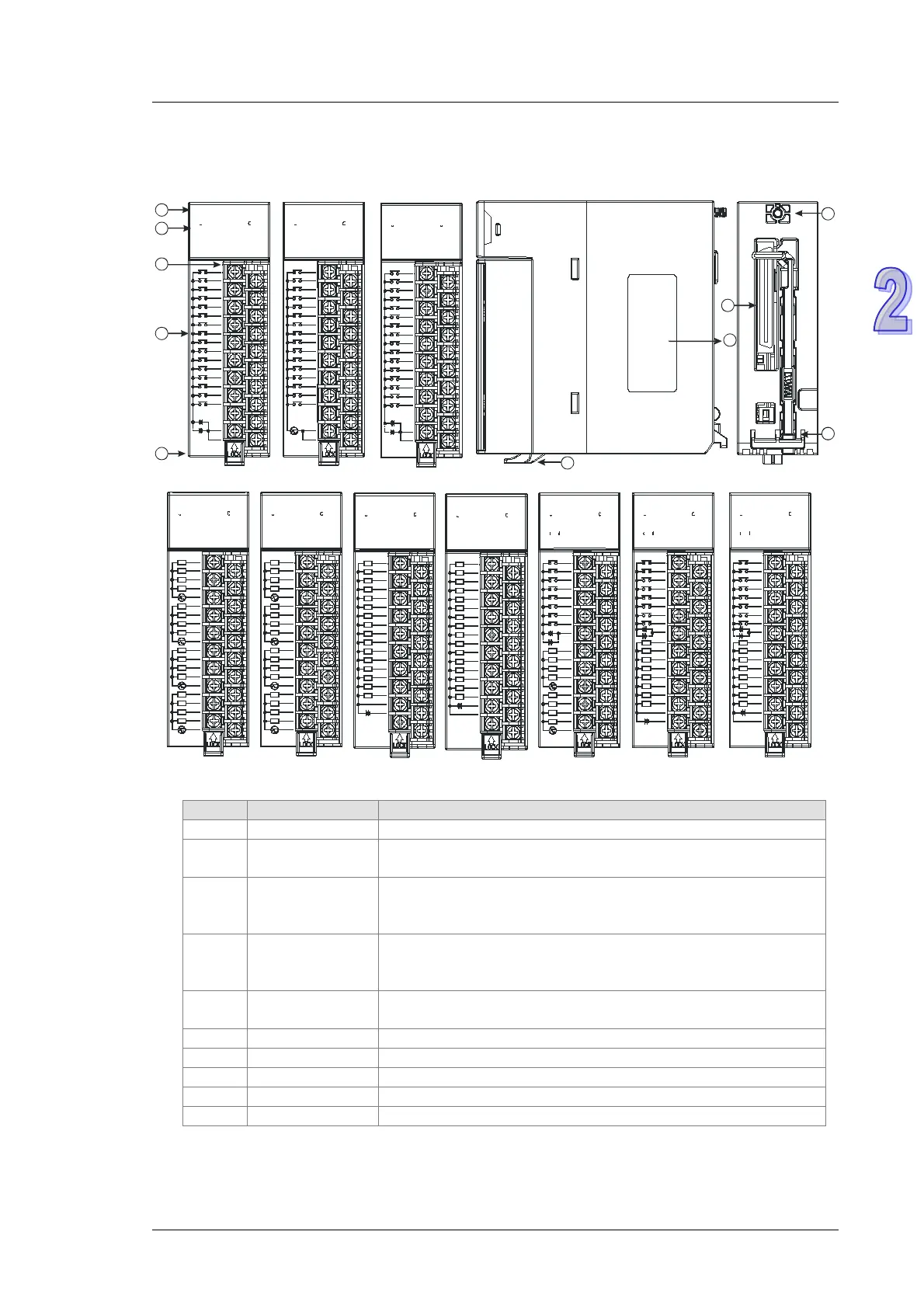
2.6.2 24BProfiles
AH16AM10N-5A/AH16AM30N-5A/AH16AR10N-5A/AH16AN01S-5A/AH16AN01R-5A/AH16AN01T-
5A/AH16AN01P-5A/AH16AP11R-5A/AH16AP11T-5A/AH16AP11P-5A
L
0
S/S
L
L
L
5
6
L
1
L
L
3
2
4
7
L
UP
ZP
0
24VDC 5mA
24VDC 0. 5A
7
6
5
4
3
2
1
0
1 2 4
5
3 6
7
0
16AP11T
21 4
5
3 6
7
10 3 4
75
62
16AM30N
1
0
4
2
12
8
14
13
15
COM
7
120/240VAC
4.5/9mA
11
9
10
COM
5
3
6
98 12 1513 1410 11
16AN01R
10 432
5
6
7
L
L
L
L
4
5
3
2
L
COM0
12
COM1
L
7
L
L
L
L
L
13
14
15
L
6
11
COM2
24VDC
/240VAC 2A
COM3
L
L
L
8
10
9
L
1
0
1110 1413 15128 9
COM3
1
L
0
L
4
L
L
5
COM0
3
L
L
2
L
8
9
L
L
10
COM1
L
7
11
13
14
L
L
L
15
12
COM2
L
L
L
6
240VAC 0.5A
16AN01S
5
210 43 6
7
98 1413 151110 12
1
3
2
0
S/S
5
6
L
L
L
L
4
7
UP
ZP
L
L
L
L
24VDC 5mA
24VDC 0. 5A
0
7
6
5
4
3
2
1
0
1 32 64
5 7
16AP11P
0 2 31 64
5 7
COM1
1
0
10 3 42
7
6
5
L
0
L
L
2
1
S/S
6
5
4
3
2
7
3
5
L
L
L
6
7
COM0
L
L
4
24VDC 5mA
240VAC 2A
16AP11R
10 432
7
6
5
1
2
3
4
7
6
8
9
10
5
10
12
11
9
8
6
5
4
3
2
15
14
7
13
S/S
24VDC
5mA
1
0
S/S
7
6
16AM10N
0 2 31
5
4
98 1510 11 12 13 14
11
21 3
109
5
13
4
12
6
7
14 15
0
2
L
L
L
L
L
0
8
1
3
4
16AN01T
9
8
7
6
10
12
13
11
ZP
UP
15
L
L
L
14
L
L
L
L
L
L
L
5
12~24VDC 0.5A
L
11
16AN01P
0
8
1
9
2
10
5
13
3 4
12
6
7
1514
L
0
1
3
L
L
4
L
L
2
12~24VDC 0.5A
8
9
L
6
7
L
L
L
10
12
L
L
13
L
L
11
ZP
L
UP
15
L
14
L
5
7
10
12
11
9
8
6
5
4
3
2
15
14
6
7
13
S/S
24VDC
5mA
1
0
16AR10N
0 2 31
5
4
S/S
98 1510 11 12 13 14
2
Input/Output LED
If there is an input signal, the input LED indicator is ON.
If there is an output signal, the output LED indicator is ON.
3
Removable
terminal block
The inputs are connected to a switch or a sensor.
The outputs are connected to a load which will be driven, e.g. a
contact, or a solenoid valve.
4
input/output
Arrangement of the terminals
5
Description of the
inputs/outputs
Number of inputs/outputs and specifications
Fixing the removable terminal block
Connecting the module and a backplane

 Loading...


