Chapter 4 Installing Hardware and Wiring
4-117
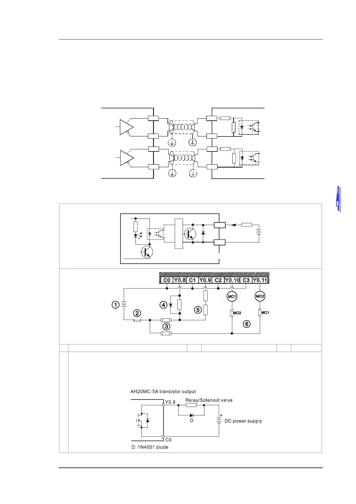
4.13.5.1 Wiring the Differential Input Terminals
The direct-current signals ranging in voltage from 5 V to 24 V can pass through the high-speed input terminals
X0.0+~X0.3+, X0.0-~X0.3-, X0.8+~X0.15+, and X0.8-~X0.15- on AH20MC-5A. The frequency of input signals
can be up to 200 kHz. These high-speed input terminals are connected to a differential (two-wire) line driver.
Wiring differential input terminals (The wiring below is used for high speed and high noise.)
A-
X0.0+
X0.0-
A+
A
B-
X0.1 +
X0.1 -
B+
B
Encoder output AH20MC-5A high speed input-
4.13.5.2 Transistor Output Circuit
Direct-current power supply
The output terminals of a transistor module are open-collector output terminals. If Y0.8 is a pulse train
output terminal of a transistor module, the output current passing through its output pull-up resistor must
be greater than 0.1 A to ensure that the transistor module operates normally.
A relay or a solenoid valve is used as a DC load. A diode is connected in parallel to absorb the surge
voltage which occurs when the load is OFF.
Transistor output
Load
Trigger circuit
Y0.8
LED
C0
AH20MC-5A
< 0.5A

 Loading...


