AH500 Hardware and Operation Manual
4-68
4.9 Wiring Analog Input/Output Modules
(1) Definitions of the terminals
◆ 2-/3-wire (passive sensor): the sensor and the system share the same power circuit.
◆ 4-wire (active sensor): the sensor uses independent power supply and suggested not to share the
same power circuit with the system.
◆ Note: use cables with the same length (less than 200 m) and use terminal resistors of less than
100 ohm.
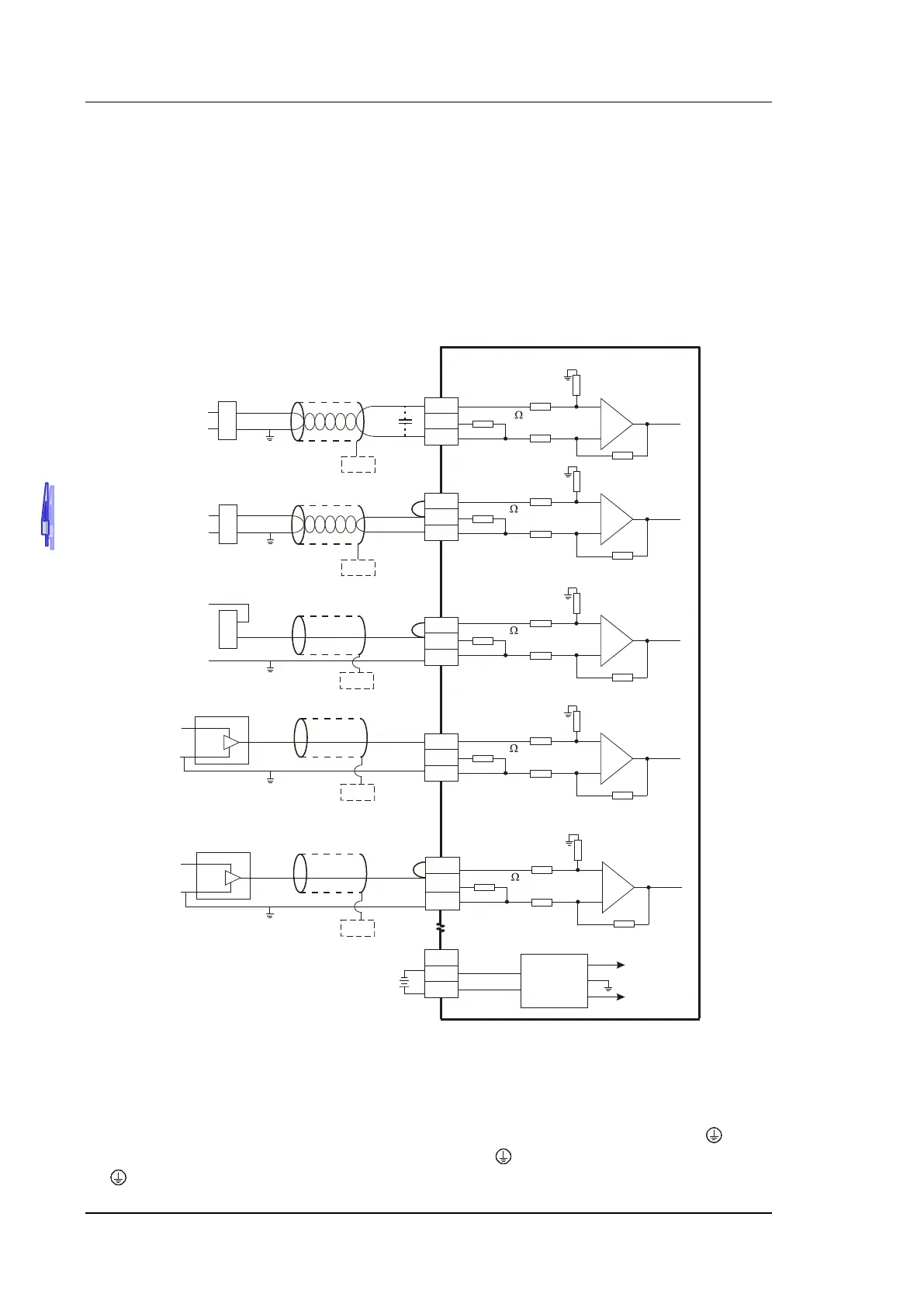
4.9.1 Wiring AH04AD-5A/AH08AD-5A
Shielded cable*1
4-wire: Voltage i nput
-10V~+10V
V0+
I0+
VI0-
CH 0
Shielded cable*1
2- wire: C urrent input
V2+
I2+
VI2-
CH2
*3
*2
CH 0
1M
CH2
AG
1M
1M
AG
1M
250
250
ZP
UP
24VDC
DC/DC
Converter
+15V
-15V
AG
SG
SG
*4
*5
+
-
Shielded c able*1
4-wire: C urrent input
-20mA~+20mA
V1+
I1+
VI1-
CH1
*2
CH1
1M
AG
1M
250
*4
SG
+
-
+
-
+24V
0V
V3+
I3+
VI3-
CH3
1M
AG
1M
250
CH 3
Shielded cable*1
3-wir e: Voltage i nput
+24V
0V
4mA~+20mA
Shielded cable*1
CH4
1M
AG
1M
250
-20mA~+20mA
3-wire: C urrent input
+24V
+
-
V4+
I4+
VI4-
CH4
*2
-10V~+10V
+24V
+
-
*4
SG
*4
SG
*4
SG
0V
+24V
0V
0V
*1. Please use shielded cables to isolate the analog input signal cable from other power cables.
*2. If the module is connected to a current signal, the terminals Vn and
In+ (n=0~7) must be short-circuited.
*3. If the ripple in the input voltage results in the noise interference with the wiring, please connect the module
to the capacitor having a capacitance in the range of 0.1 μF to 0.47 μF with a working voltage of 25 V.
*4. Please connect the shielded cable to the terminal SG.
*5. Once AH04AD-5A is installed on a backplane, the terminal SG on AH04AD-5A and the terminal
on the
backplane will be short-circuited. Please connect the terminal on the backplane to the ground terminal
.

 Loading...


