Chapter 4 Installing Hardware and Wiring
4-73
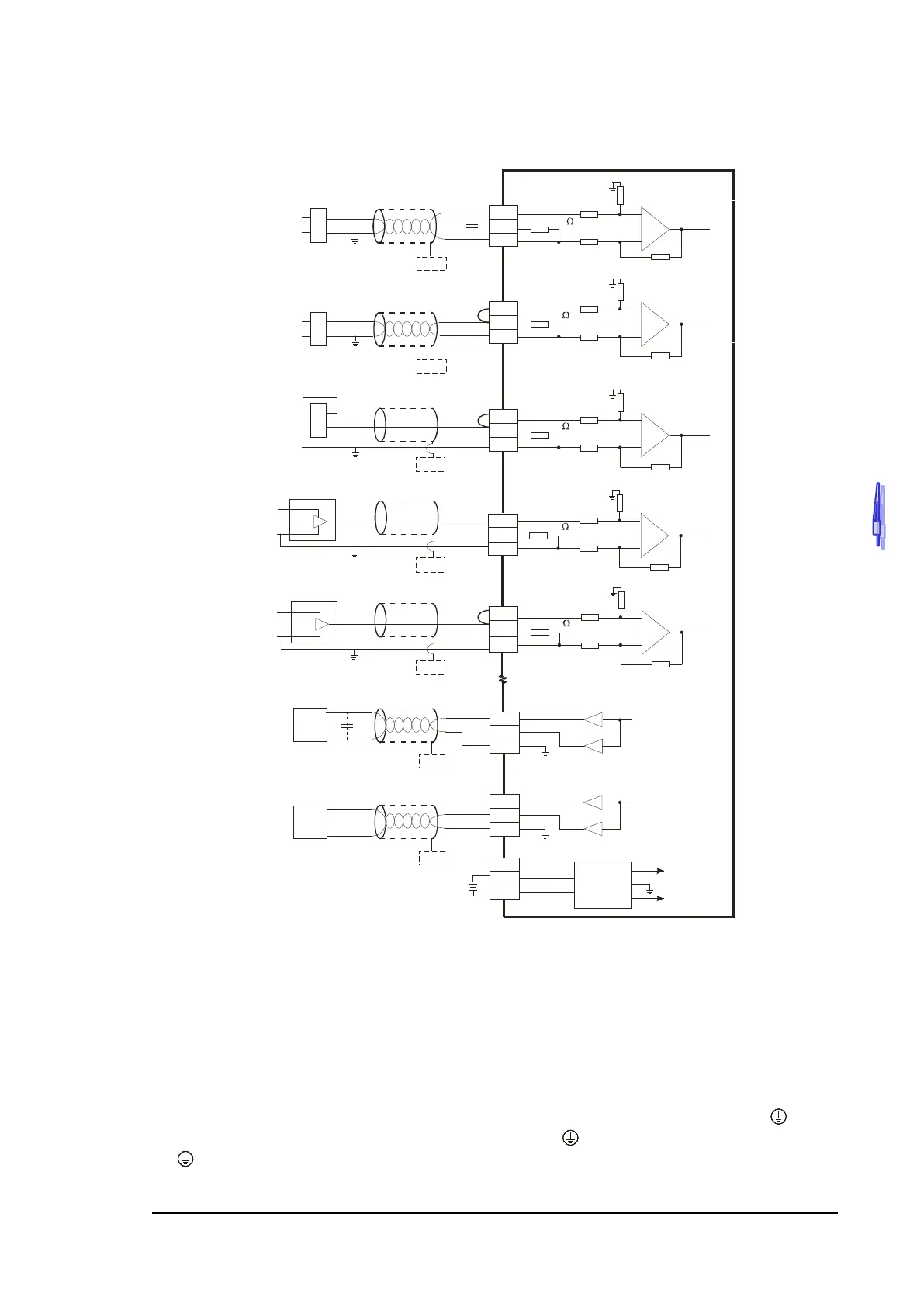
4.9.7 Wiring AH06XA-5A
CH0
1M
CH1
AG
1M
1M
AG
1M
250
250
VO1
IO1
AG
CH1
0mA~20mA
CH1
AG
VO0
IO0
AG
CH0
-10V~+10V
*5
CH0
AG
ZP
UP
24VDC
DC/DC
+15 V
-1 5V
AG
S G
* 7
*6
*6
SG
SG
CH2
1M
AG
1M
250
-10V~+10V
V0+
I0+
VI 0-
CH0
V2+
I2+
VI2-
CH2
*3
*2
SG
*6
+
-
-20mA ~+20mA
V1+
I1+
VI1-
CH1
*2
*6
SG
+
-
+
-
+24V
0V
+24V
0V
4mA~+20 mA
*6
SG
+24V
0V
V3 +
I3+
VI3-
CH3
1M
A G
1M
250
CH3
CH4
1M
A G
1M
250
-2 0mA~+2 0mA
+24V
+
-
V4+
I4+
VI4-
CH4
*2
-10V~+10V
+24V
+
-
*6
SG
*6
SG
0V
0V
AC motor dri ve,
recorder,
proportioning v alve
Converter
4-wire: Voltage I nput
Shielded c able * 1
Shielded c able * 1
Shielded c able * 1
Shielded c able * 1
4-wire: Current Input
2-wir e: Current Input
3-wire: C urrent Input
3-wire: Voltage I nput
Shielded c able * 1
Current output
Shielded c able * 4
AC motor dri ve,
recorder,
proportioning v alve
Shielded cable * 4
Voltage output
*1. Please isolate the analog input signal cable from other power cables.
*2. If the module is connected to a current signal, the terminals V1+ and I1+ must be short-circuited, and the
terminals V2+ and I2+ must be short-circuited.
*3. If the ripple in the input voltage results in the noise interference with the wiring, please connect the module
to the capacitor having a capacitance in the range of 0.1 μF to 0.47 μF with a working voltage of 25 V.
*4. Please isolate the analog output signal cable from other power cables.
*5. If a ripple is large for the input terminal of the load and results in the noise interference with the wiring,
please connect the module to the capacitor having a capacitance in the range of 0.1 μF to 0.47 μF with a
working voltage of 25 V.
*6. Please connect the shielded cables to the terminal SG.
*7. Once AH06XA-5A is installed on a backplane, the terminal SG on AH06XA-5A and the terminal
on the
backplane will be short-circuited. Please connect the terminal on the backplane to the ground terminal
.

 Loading...


