Chapter 2 Specifications and System Configuration
2-11
(The user program, the CPU paramter, the module
table, and the setting values in the devices are
backupped from the memory card to the CPU module.)
SW4
It is used with SW3.
OFF: When the system is backupped, the values in the
devices are backupped.
ON: When the system is backupped, the values in the devices
are not backupped.
9 RST button
Resetting the CPU module, and restoring it to the default factory
value
Clearing the value in the latched device
11 RUN/STOP switch
RUN: The user program is executed.
STOP: The execution of the user program stops.
Connecting the module and a backplane.
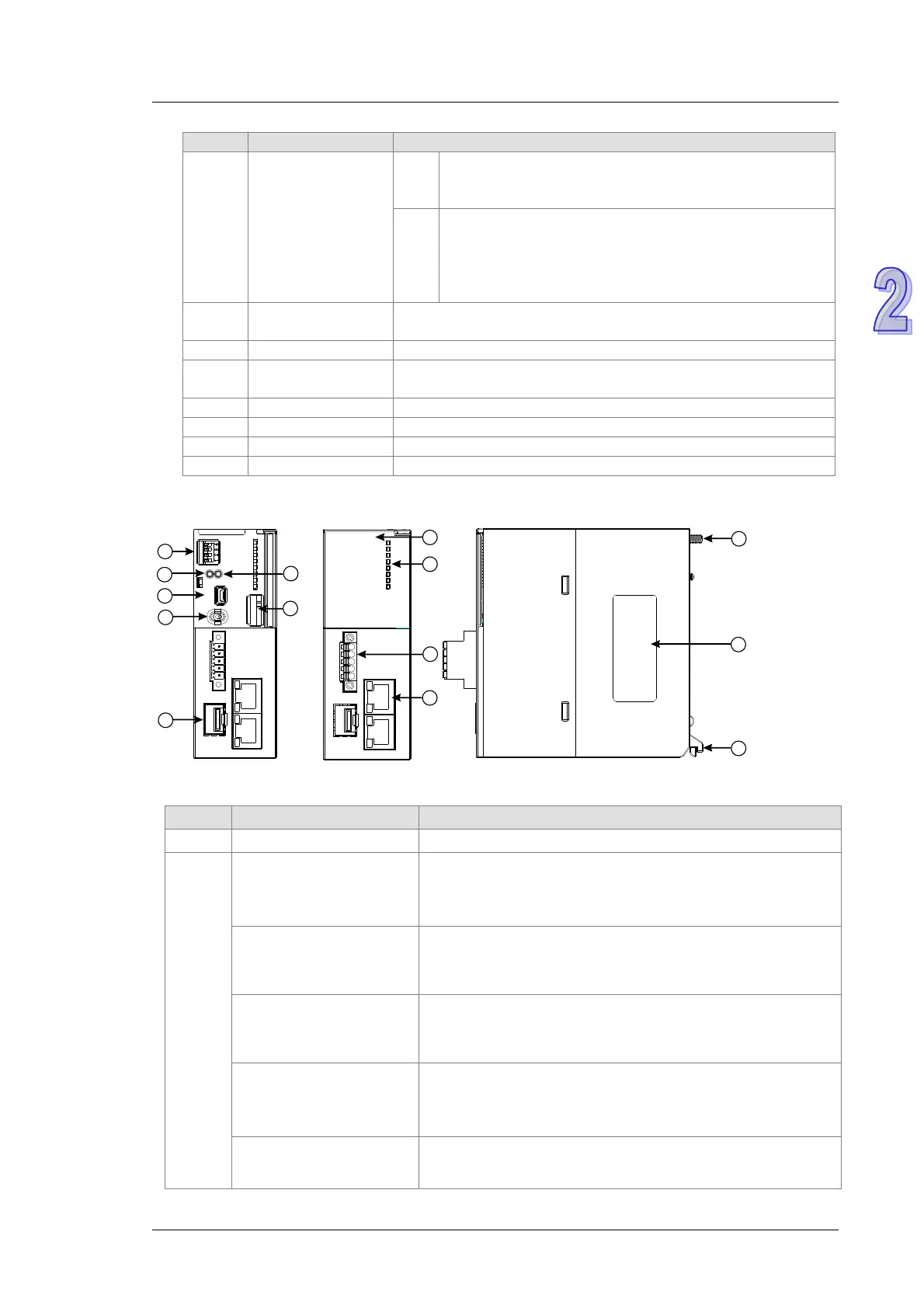
2.2.4.2 AH500 Redundant CPU Modules
1
2
3
4
10
Ethernet
SY NC
D-
D+
SG
RX
TX
R UN
ER R.
B FLT
SYS.
COM
MST.
SY NC
C LRRST
RU NSTO P
U SB
RUN
ERROR
BUS FAU LT
S YSTEM
C OM
MASTER
SYNC
Ether ne t
SY NC
D-
D+
SG
RX
TX
C P U5 60 -EN 2
11
6
12
5
7
8
9
14
13
1
Shows the model name of the CPU module.
2
Run/Stop LED
Operating status of the CPU
ON: the module is running
OFF: the module stops
Blinking: the program is checking if there is any error
Error LED
ON: a serious error occurs in the module.
OFF: the module is normal.
Blinking: a minor error occurs in the module.
Bus Fault LED
ON: a serious error occurs in the I/O Bus.
OFF: the I/O Bus is normal.
Blinking: a minor error occurs in the I/O Bus.
SYSTEM LED
Indicates the system status of the CPU
ON: external I/O is locked
OFF: system in default
Blinking: reset/clear
COM LED
Indicates the communication status of the COM port.
OFF: no communication over the COM port
Blinking: communication over the COM port

 Loading...


