PFD Operation
SkyView HDX Pilot’s User Guide – Revision B 4-19
Some radios, such as the Garmin SL30, provide information about standby
frequencies that can be loaded into bearing pointer locations. These are only
available for standby VORs that are within range and are labeled as SBY bearing
pointers.
NAV radios tuned to a LOC/ILS frequency do not provide bearing information due to the nature
of the localizer radio signal.
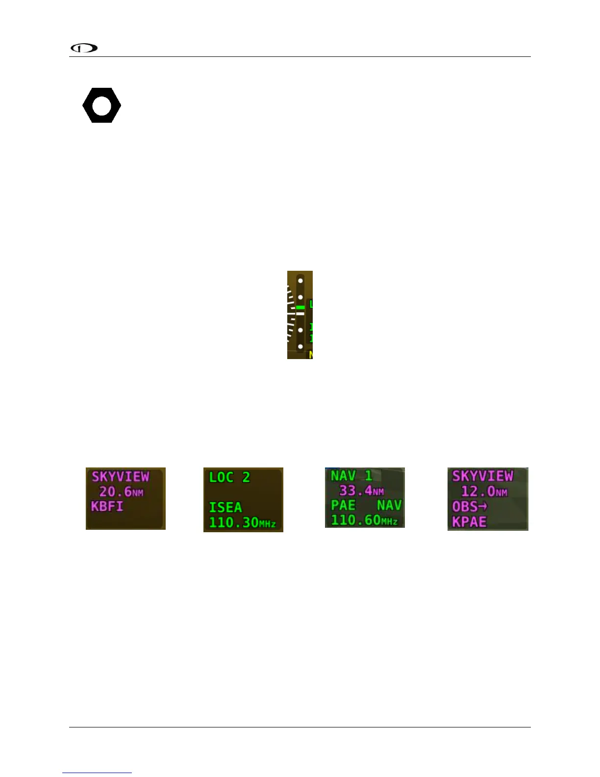
Glideslope/VNAV Indicator
A glideslope indicator, as depicted in Figure 52 below, will appear immediately to the right of
the HSI when the selected HSI is transmitting valid vertical guidance data, such as a NAV radio
tuned to an ILS or a GPS with vertical navigation output.
Figure 52 – HSI Glide Slope
When displaying an ILS glideslope, full deflection of the vertically moving indicator bar is 0.5
degrees.
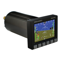
HSI Info Items
Figure 54
HSI NAV Info
(LOC Example)
Figure 56
OBS Mode
Active
Textual info items that provide additional data about the HSI source are displayed to the right
of the HSI display, and right of the glideslope indicator if it is shown. The information available
depends on the data being provided by the HSI source. Examples of info items that may be
displayed include DTW (distance to waypoint), ID (VOR identifier), and frequency. When a NAV
radio decodes the identifier for a frequency, SkyView displays it in the HSI info area and tries to
match the identifier to the same one in its aviation database. When it finds a match, it displays
Virtual-DME (non-certified) distance in magenta.