PFD Operation
SkyView HDX Pilot’s User Guide – Revision B 4-5
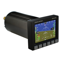
Airspeed Indicator
The Airspeed Indicator is displayed on the left side of the
PFD and incorporates an airspeed tape with a digital
readout, true airspeed (TAS), airspeed trend indicator,
and airspeed bug. Figure 30 is an example Airspeed
Indicator.
Units can be set to miles per hour, nautical miles per hour
(knots), or kilometers per hour. Reference the SkyView
Classic / SE / HDX System Installation Guide for
instructions on how to change the displayed units.
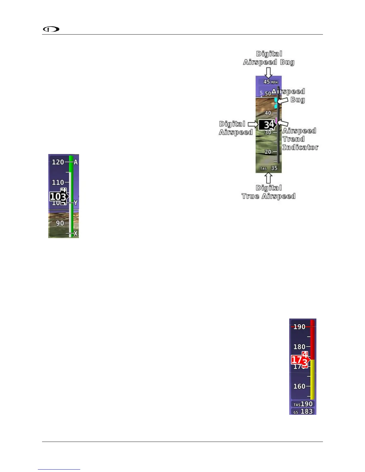
The airspeed tape displays indicated airspeed including
gray, white, green, yellow, and red ranges
to provide a graphical representation of
aircraft speed in relation to the aircraft's
limits. These ranges are controlled by
setting the airspeed limitations for the
aircraft. Performance speeds (Vx, Vy and
Va) are displayed as a letter on the right
side of the airspeed tape. Reference the
SkyView Classic / SE / HDX System Installation Guide for instructions on how to
configure the airspeed limitation color thresholds.
Airspeed will display “---” at zero through 20 knots, at which point it will become live. Once live,
it will display airspeeds down to 15 knots. Below 15 knots, “---” will again be displayed.
The indicated airspeed (IAS) digits scroll up and down, simulating an analog Airspeed Indicator.
The rate of change of the digits provides a sense of the increase or decrease in speed.
The airspeed trend indicator is displayed as a magenta bar on the airspeed tape. It grows
proportionally in the direction of the rate of change (acceleration or deceleration). The airspeed
trend indicator is scaled to indicate a 6-second airspeed trend which means
that if the acceleration is kept constant, the airspeed will end up at the
number indicated at the end of the trend line after 6 seconds have passed.
True Airspeed (TAS) is digitally displayed at the bottom of the airspeed tape.
If configured with a GPS, Ground Speed (GS) is also displayed under the True
Airspeed.
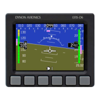
In some aircraft, Vne (Redline) is limited by TAS instead of IAS. When
configured to indicate Vne as TAS, the Red airspeed range will dynamically
adjust so that the TAS limit is what starts the red airspeed range. Additionally,
a Red marker is shown at the IAS that Vne would be at when at sea-level on a
standard day, which is when TAS equals IAS. This lets you quickly see the
difference between your current Vne as TAS and Vne as IAS. In the example
Figure 31 – Example