Setup Requirements
Adapter Wiring and Signal Assignments
2-8 Matrix E1 Series (1G694-13) Configuration Guide
2.2 USING A TELNET CONNECTION
Once the Matrix E1 device has a valid IP address, you can establish a Telnet session from any
TCP/IP based node on the network.
For information about setting the IP address, refer to Section 3.2.2.11.
Refer to the instructions included with the Telnet application for information about establishing a
Telnet session.
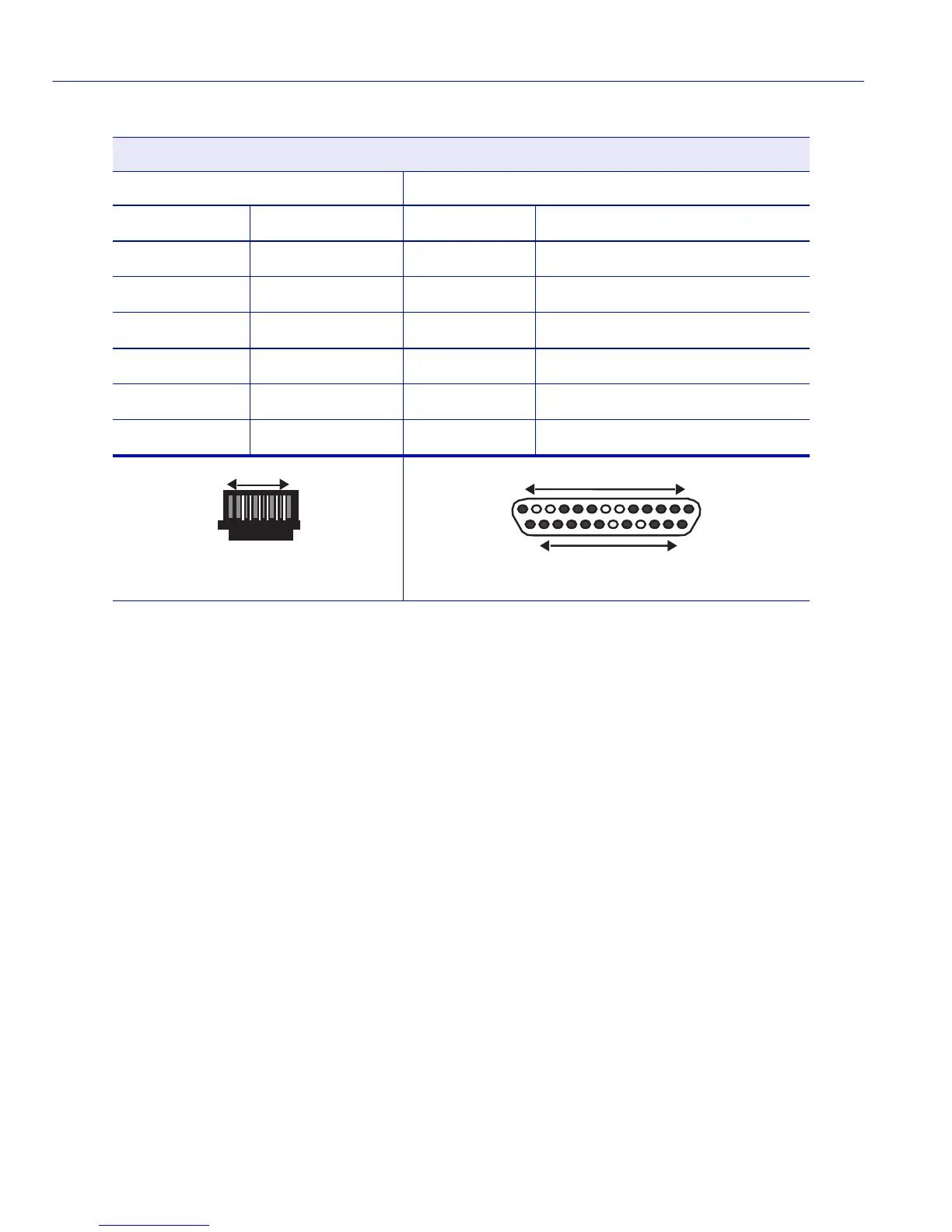
Modem Port Adapter Wiring and Signal Diagram
RJ45 DB25
Pin Conductor Pin Signal
1 Blue 2 Transmit (TX)
2 Orange 8 Data Carrier Detect (DCD)
4 Red 3 Receive
5 Green 7 Ground (GRD)
6 Yellow 20 Data Terminal Ready (DTR)
8 Gray 22 Ring Indicator
RJ45 Connector (Female)
Pins
81
045905
Pins
DB25 Connector (Male)
045907
131
2514