Setup Requirements
Adapter Wiring and Signal Assignments
Matrix E1 Series (1G694-13) Configuration Guide 2-7
2.1.5 Adapter Wiring and Signal Assignments
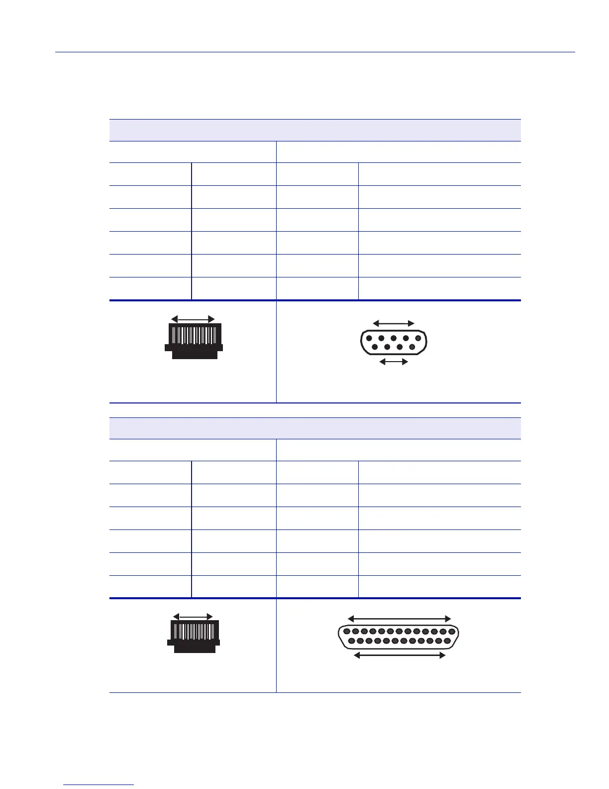
Console Port Adapter Wiring and Signal Diagram
RJ45 DB9
Pin Conductor Pin Signal
1 Blue 2 Receive (RX)
4 Red 3 Transmit (TX)
5 Green 5 Ground (GRD)
2 Orange 7 Request to Send (RTS)
6 Yellow 8 Clear to Send (CTS)
VT Series Port Adapter Wiring and Signal Diagram
RJ45 DB25
Pin Conductor Pin Signal
4 Red 2 Transmit (TX)
1 Blue 3 Receive (RX)
6 Yellow 5 Clear to Send (CTS)
5 Green 7 Ground (GRD)
2 Orange 20 Data Terminal Ready
RJ45 Connector (Female)
Pins
81
045905
69
DB9 Connector (Female)
15
Pins
045904
RJ45 Connector (Female)
Pins
81
045905
DB25 Connector (Female)
Pins
045906
25
14
13 1