Port Configuration
Port Assignment Scheme
4-2 Matrix E1 Series (1G694-13) Configuration Guide
4.1.1 Port Assignment Scheme
The expansion module and fixed front panel port numbering scheme used when configuring
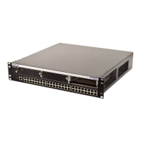
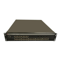
Matrix E1 1G694-13 port functionality is shown in Figure 4-1. Ports 1 through 12 are designated
as 0 for being fixed ports on the front panel. In this numbering scheme, front panel port 8 is
expressed as 0.8 in the CLI syntax.
The device’s optional 10-Gigabit Ethernet expansion module slot (location 1) is designated as 1.1
in the CLI syntax. Figure 4-2 shows the expansion modules available at the time of this printing.
For information on how this device’s port assignment scheme is expressed in CLI syntax, refer to
Section 4.1.2.
Table 4-1 Optional Ethernet Expansion Modules, Compliance, and Physical Connection
Ethernet Expansion Module Compliant to Physical Connection
ZPIM1-01 10-Gigabit Ethernet One fixed SC connector
ZPIM1-06 10-Gigabit Ethernet One slot for an optional
10-Gigabit Ethernet (10 GbE)
module with one fiber optic SC
connector. This module must
conform to the XENPAK 10
GbE standard.
 Loading...


