Setup Requirements
Connecting to a VT Series Terminal
Matrix E1 Series (1G694-13) Configuration Guide 2-3
5. When these parameters are set, the Matrix E1 startup screen will display.
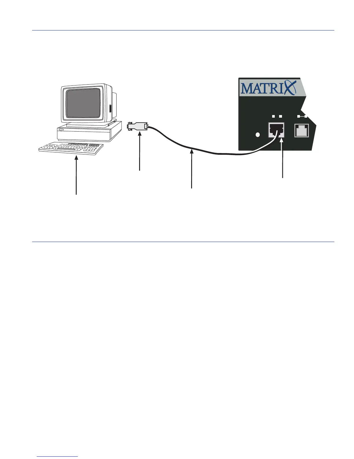
Figure 2-1 Connecting an IBM PC or Compatible Device
2.1.3 Connecting to a VT Series Terminal
To connect a VT series terminal to an Enterasys Networks switch console port (Figure 2-2), use a
UTP cable with RJ45 connectors and an optional RJ45-to-DB25 female adapter (PN 9372110),
and proceed as follows:
1. Connect the RJ45 connector at one end of the cable to the console port on the Enterasys
Networks device.
2. Plug the RJ45 connector at the other end of the cable into the RJ45-to-DB25 female adapter.
Refer to Section 2.1.5 for adapter wiring and signal assignments.
3. Connect the RJ45-to-DB25 adapter to the port labeled COMM on the VT terminal.
➀
PC
➂
UTP Cable with RJ45 Connectors
➁
RJ45-to-DB9 PC Adapter
➃
RJ45 Console Port
1
Reset
Console
CPUPWR
1G694-13
3712_20
Á
Â
Ã
À