1-5
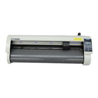
Rear view: CE8000-40
Power switch
AC line inlet
Roll-medium tray guide rail
Roll-medium tray
Media sensor
USB memory dedicated connector
USB interface connector
Wired LAN interface
Accessory case
Wireless LAN module connection terminal
Power switch .............................Used to turn the plotter on and off.
AC line inlet ...............................Inlet where the power cable is connected.
Roll-medium tray .......................A tray to set media in.
Roll-medium tray guide rail ........A rail to set the roll media tray in.
Accessory case .........................Space for temporary storage of accessories such as cutter blades and cutter
plungers.
* The accessory case has a magnet. Please attach it in a convenient location.
Media sensor .............................Used to scan the trailing edge of the media.
USB interface connector ...........Used to connect the plotter to the computer with a USB interface cable.
Wireless LAN module connection terminal
.............................................This is the terminal for connecting the wireless LAN module to the plotter.
* A cover is attached to protect the terminals at the time of purchase.
Wired LAN interface ..................This connector is used when connecting this plotter via network (wired LAN).
* Wired LAN unit is factory-installed option.
USB memory dedicated connector
.............................................This is a dedicated connector for USB memory.