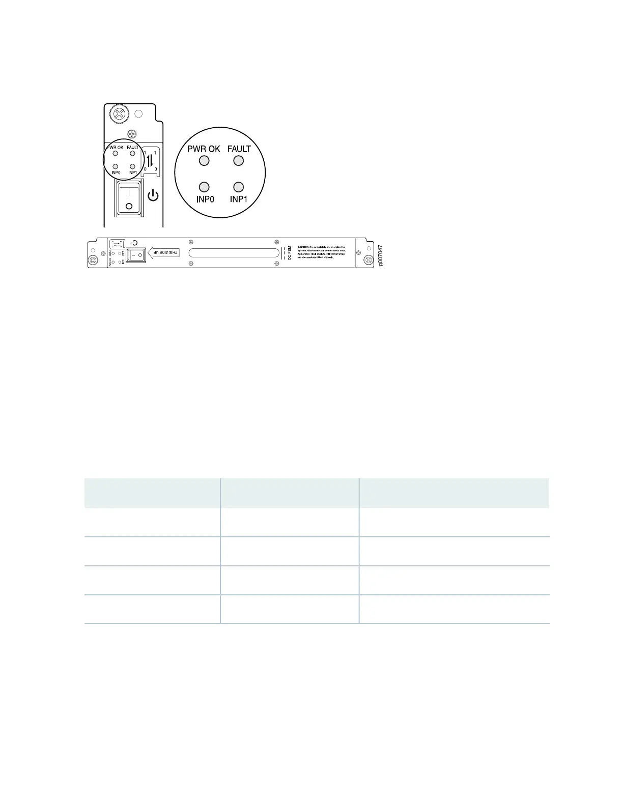
Figure 50: DC Power Supply Module
The DC power subsystem is feed redundant. Each DC PSM can be connected to two separate feeds from
different sources that are used to provide feed redundancy. If two feeds are connected, PSM input power
will be drawn from the feed with the higher voltage present. There are two PDMs per power subsystem
capable of carrying nine feeds each. Connect feeds from one source to one PDM and feeds from the other
source to the second PDM of the power subsystem. The primary input of the PSM is a dual redundant
feed, INP0 and INP1. Both feeds are active during operation, but both feeds may or may not be providing
current. Move the input mode DIP switch to the on or off position to determine the power supply feeds
(see Table 32 on page 113 and Figure 51 on page 114). In addition, a PSM failure triggers the alarm LED on
the craft interface. Each PDM has an LED per feed indicating whether the feed is active or not, or whether
the feed is connected properly, see “MX2000 Router DC Power Subsystem Electrical Specifications” on
page 205.
Table 32: DIP Switch Positions on the DC PSM
Input SourceRight Switch PositionLeft Switch Position
NoneOffOff
Input 0 (INP0)OffOn
Input 1 (INP1)OnOff
Both Input 0 and Input 1OnOn
113