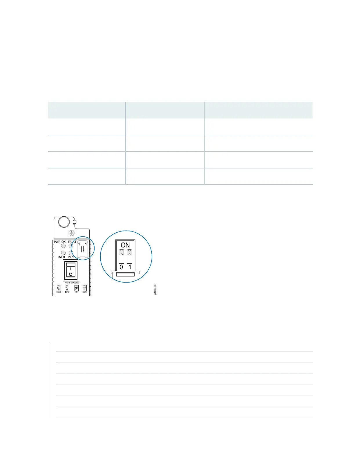
current. Move the input mode DIP switch to the on or off position to determine the power supply feeds
(see Table 32 on page 113 and Figure 51 on page 114). In addition, a PSM failure triggers the alarm LED on
the craft interface. Each PDM has an LED per feed indicating whether the feed is active or not, or whether
the feed is connected properly, see “MX2000 Router DC (240 V China) Power Subsystem Electrical
Specifications” on page 207.
Table 33: DIP Switch Positions on the DC PSM
Input SourceRight Switch PositionLeft Switch Position
NoneOffOff
Input 0 (INP0)OffOn
Input 1 (INP1)OnOff
Both Input 0 and Input 1OnOn
Figure 53: Selecting Input Feed on the DC Power Supply Module (240 V China)
RELATED DOCUMENTATION
MX2020 DC and Power Supply Module LEDs | 117
MX2000 DC Power Distribution Module (240 V China) LEDs | 111
MX2000 Router Grounding Specifications | 138
DC Power (-48 V) Circuit Breaker Requirements for the MX2020 Router | 215
MX2000 DC Power Distribution Module (240 V China) Description | 109
DC Power Cable Specifications for the MX2020 Router | 216
Site Electrical Wiring Guidelines for MX Series Routers
116